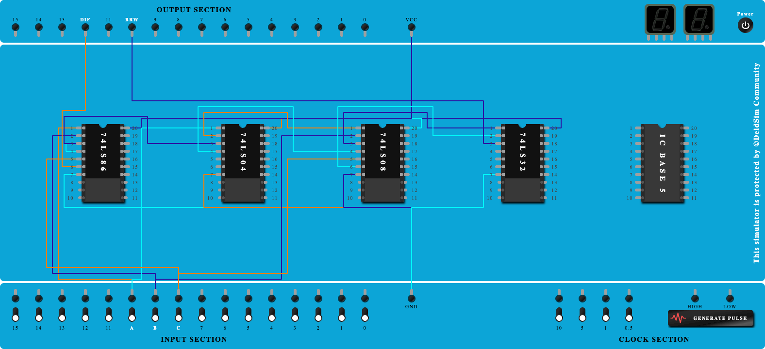
Full Subtractor using Two half adders basic gates

100%
Step-by-Step Procedure
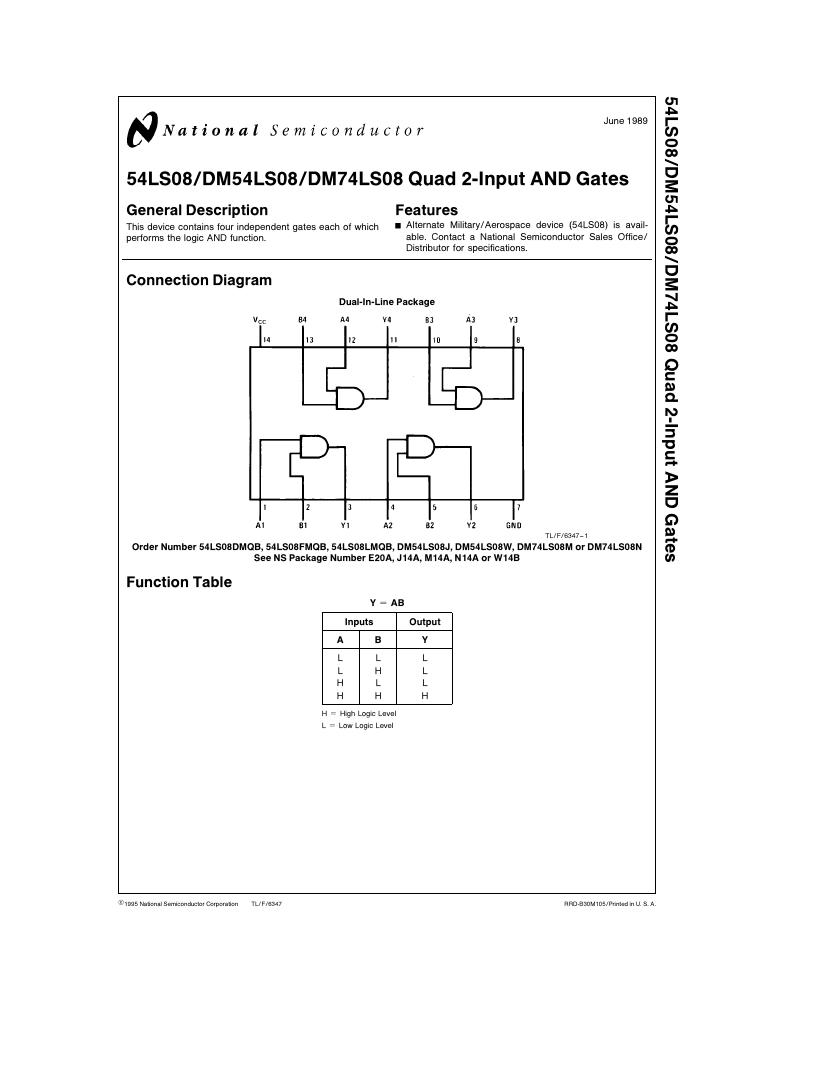
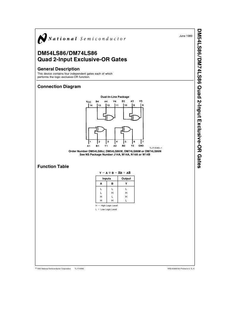
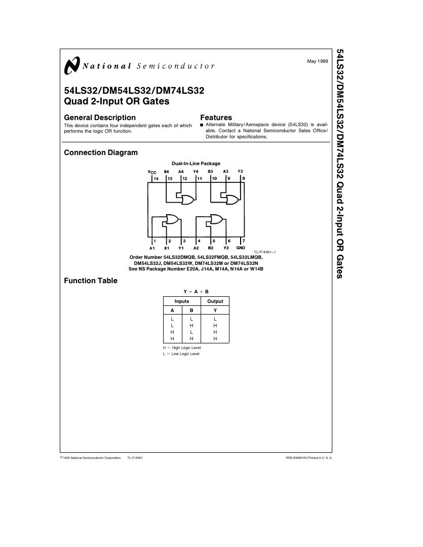
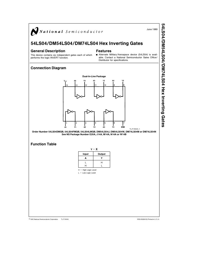
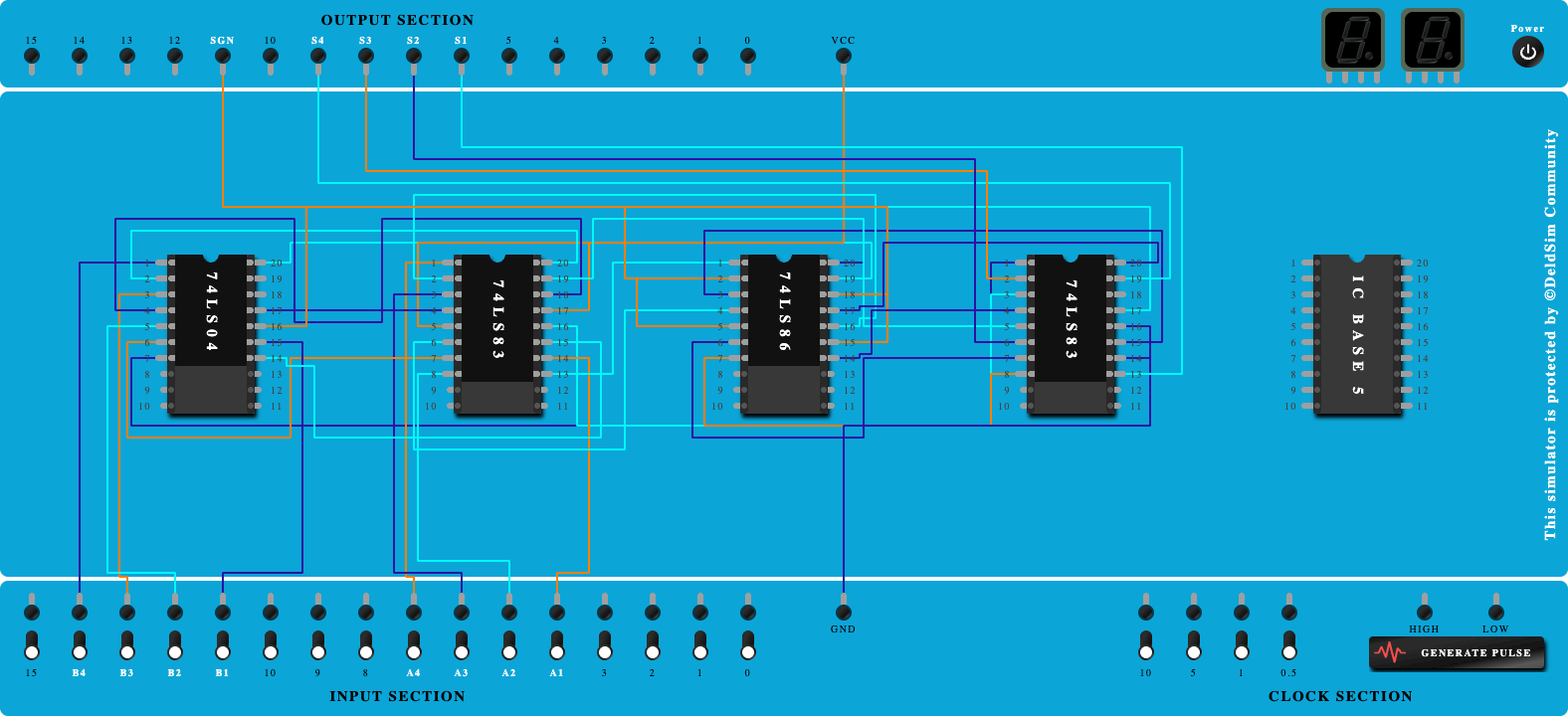
- Click on 'Next' button to Add IC-74LS04,74LS86,74LS08,74LS32
- Click on 'Next' button to Connect GND and VCC of all ICs
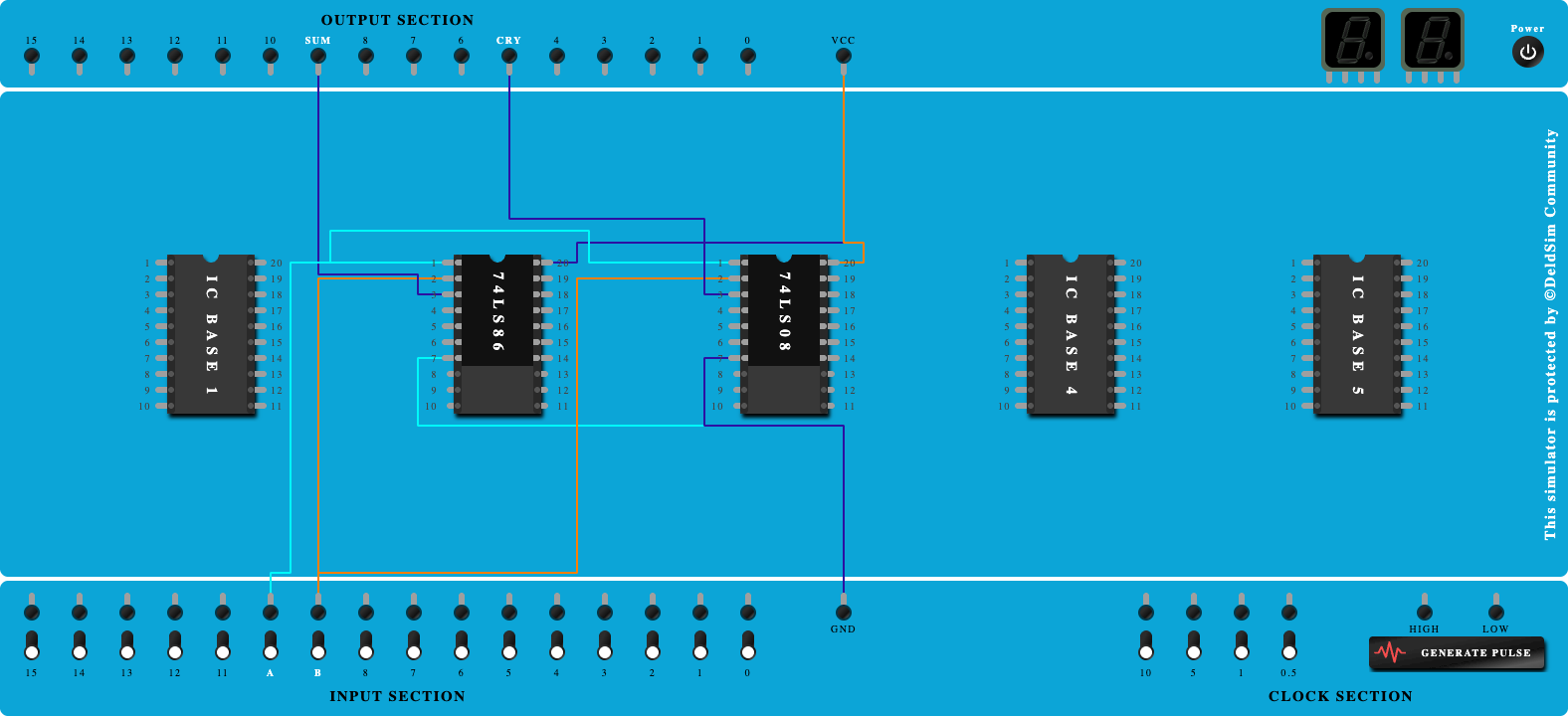
- Click on 'Next' button to Connect Input 'A' to Pin-1 of Ex-OR Gate
- Click on 'Next' button to Connect Input 'B' to Pin-2 of Ex-OR Gate
- Click on 'Next' button to Connect Input 'A' to Pin-1 of NOT Gate
- Click on 'Next' button to Connect Output of NOT Gate-1 to Pin-1 of AND Gate
- Click on 'Next' button to Connect Input 'B' to Pin-2 of AND Gate
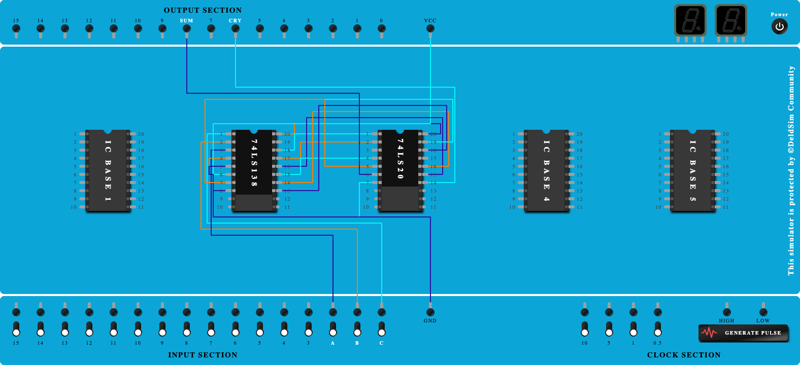
- Click on 'Next' button to Connect Output of EX-OR Gate-1 to Input Pin-1 of EX-OR Gate-2
- Click on 'Next' button to Connect Input 'C' to Input Pin-2 of EX-OR Gate-2
- Click on 'Next' button to Connect Output of EX-OR Gate-1 to Input Pin-1 of NOT Gate-2
- Click on 'Next' button to Connect Output of NOT Gate-2 to Input Pin-1 of AND Gate-2
- Click on 'Next' button to Connect Input 'C' to Input Pin-2 of AND Gate-2
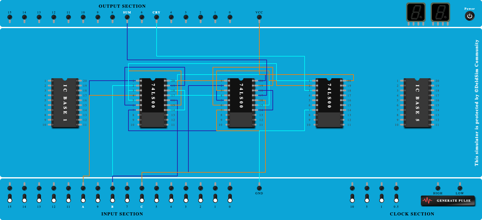
- Click on 'Next' button to Connect Output of AND Gate-1 to Pin-1 of OR Gate
- Click on 'Next' button to Connect Output of AND Gate-2 to Pin-2 of OR Gate
- Click on 'Next' button to Connect Output of EX-OR Gate-2 to output port as 'Difference'
- Click on 'Next' button to Connect Output of OR Gate to output port as 'Borrow'