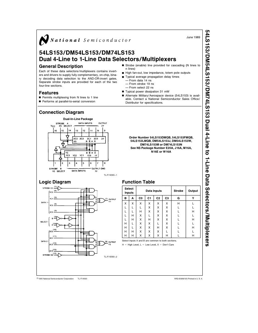
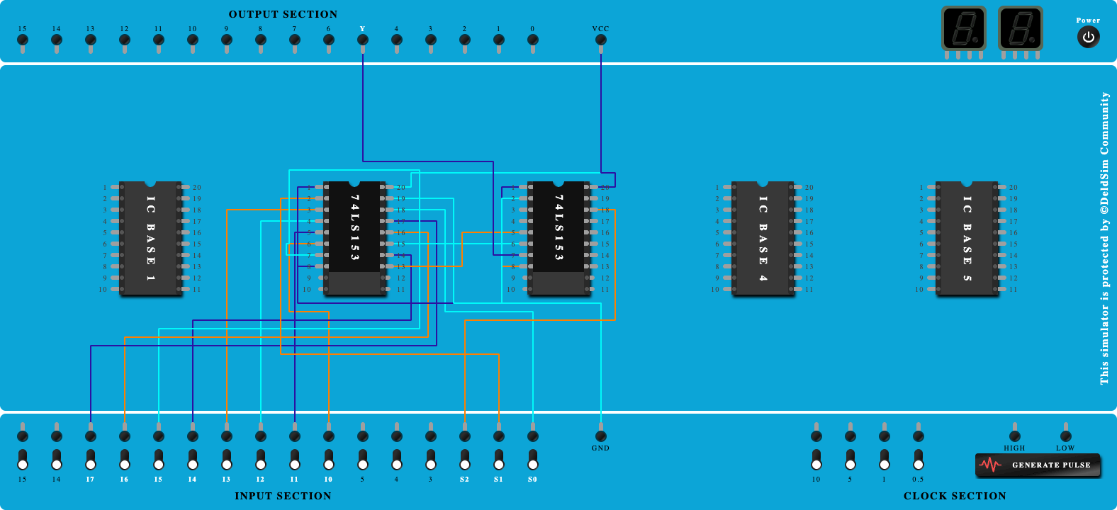
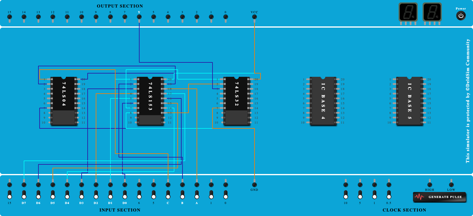
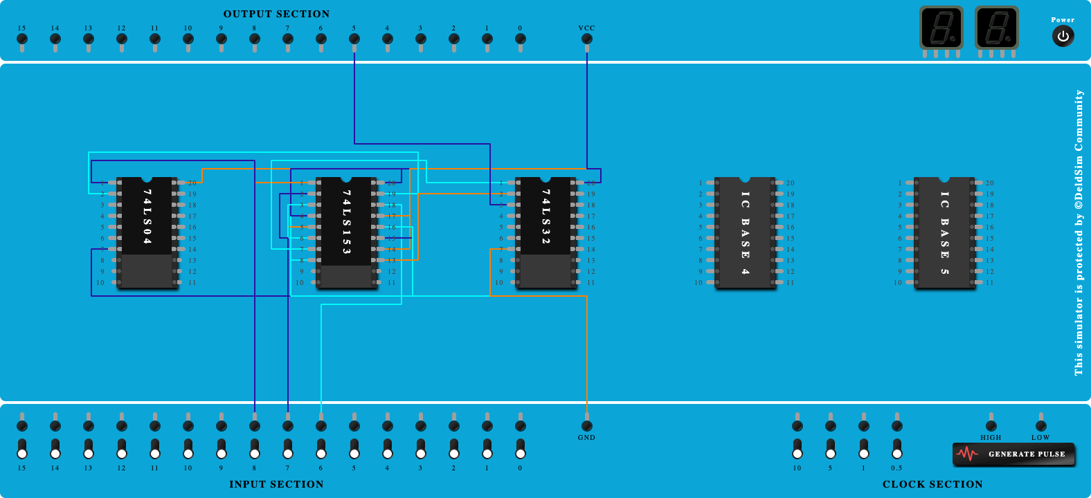
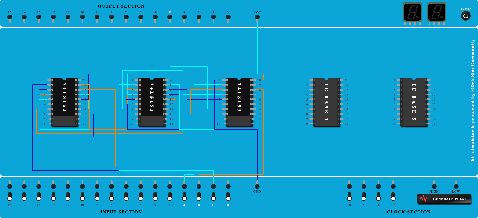
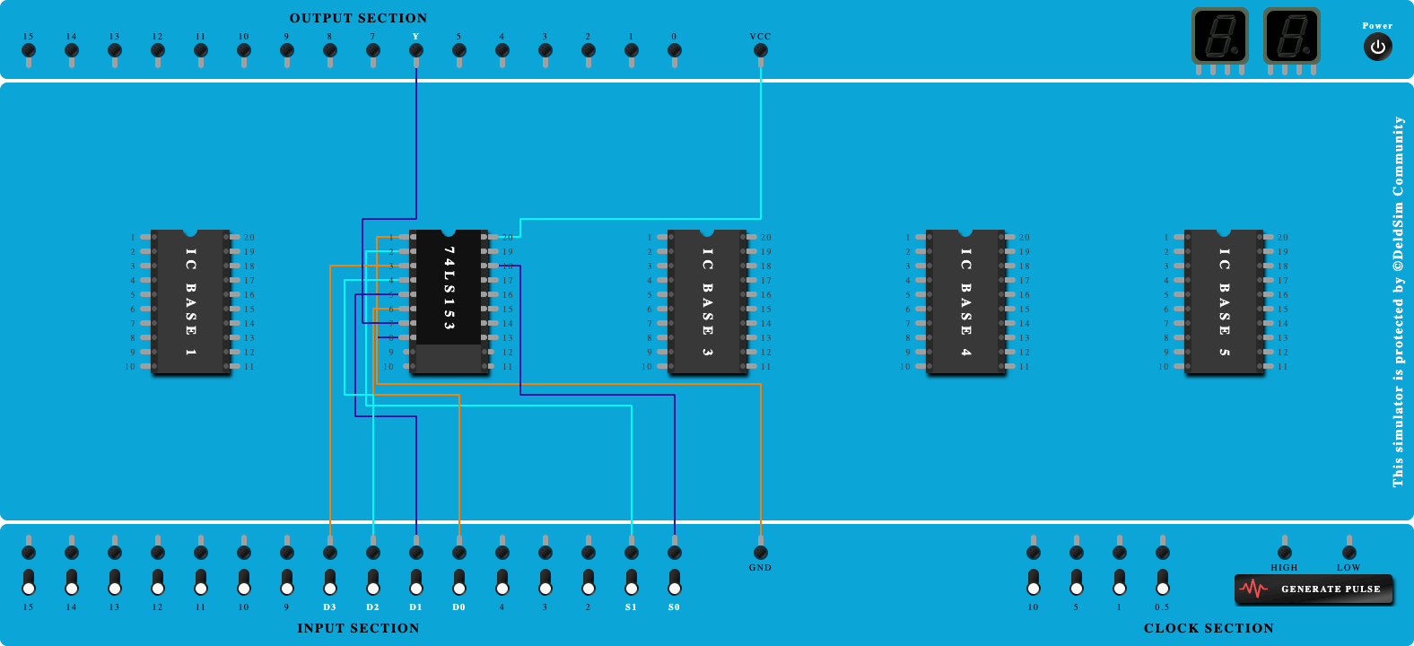
4:1 Multiplexer Using IC 74LS153

100%
Step-by-Step Procedure
- Click on 'Next' button to Add IC-74LS153
- Click on 'Next' button to Connect GND and VCC of IC
- Click on 'Next' button to Connect 'G' to GND
- Click on 'Next' button to Connect 'S0' to Pin-14
- Click on 'Next' button to Connect 'S1' to Pin-2
- Click on 'Next' button to Connect Input 'D0' to Pin-6
- Click on 'Next' button to Connect Input 'D1' to Pin-5
- Click on 'Next' button to Connect Input 'D2' to Pin-4
- Click on 'Next' button to Connect Input 'D3' to Pin-3
- Click on 'Next' button to Connect Output 'Y' to Output Port