Learning Objectives
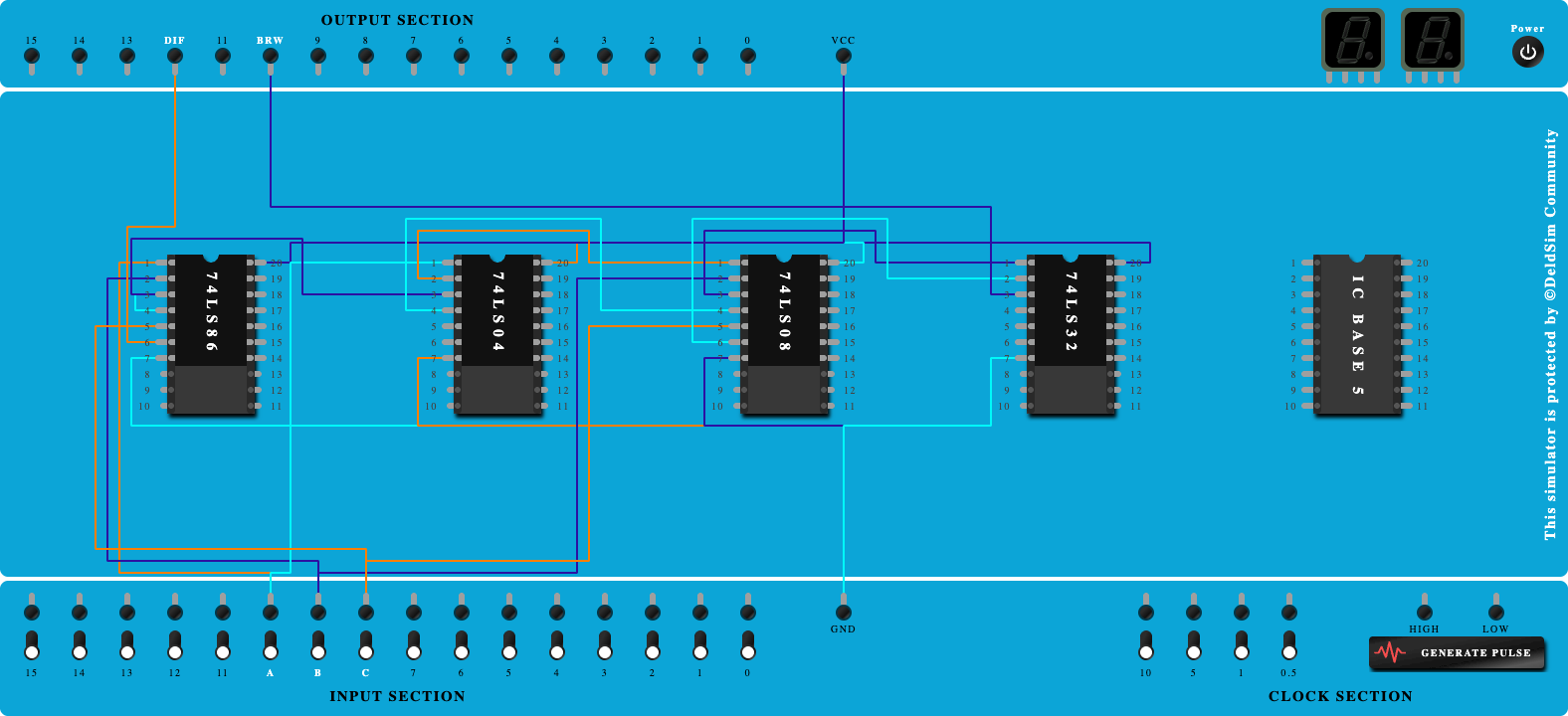
- To understand the behavior and demonstrate Full Subtractor using Two half adders basic gates.
- To apply knowledge of the fundamental gates to create truth tables.
- To develop digital circuit building and troubleshooting skills.
- To understand key elements of TTL logic specification or datasheets.
Integrated Circuits Used
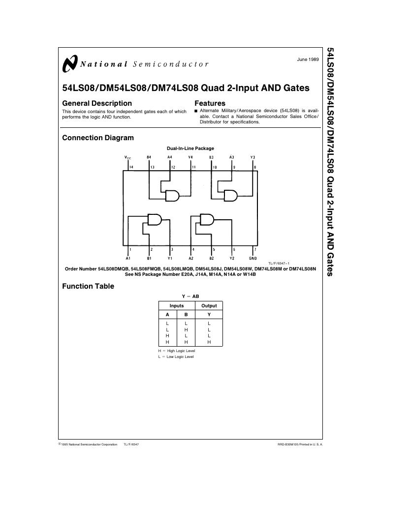
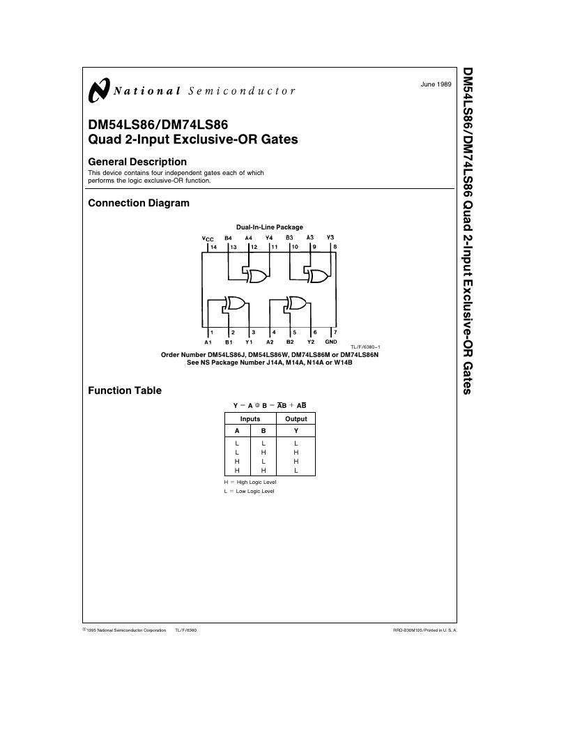
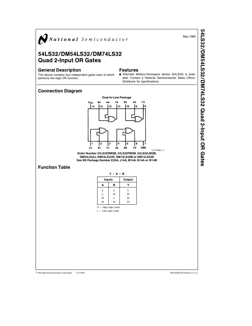
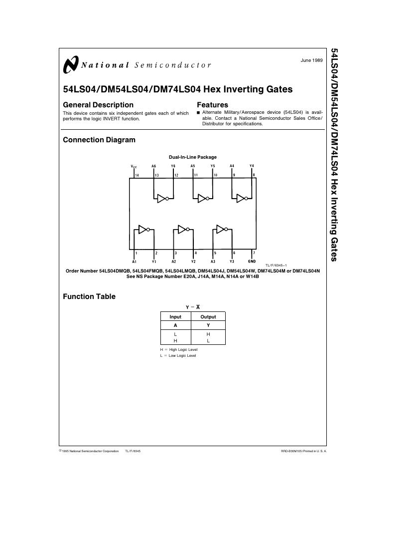
Circuit Tutorials
Procedure
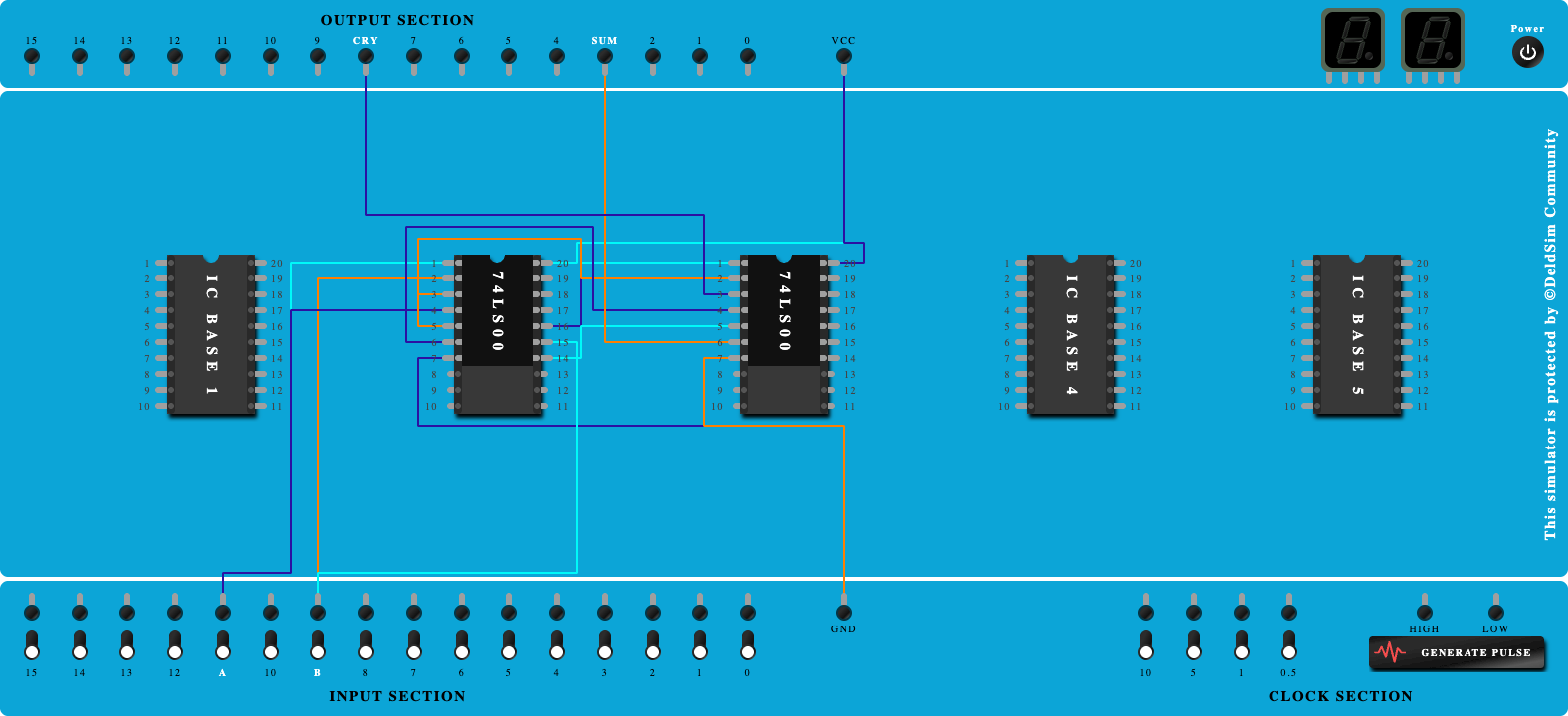
- Place the IC on IC Trainer Kit.
- Connect VCC and ground to respective pins of IC Trainer Kit.
- Implement the circuit as shown in the circuit diagram.
- Connect the inputs to the input switches provided in the IC Trainer Kit.
- Connect the outputs to the switches of O/P LEDs
- Apply various combinations of inputs according to the truth table and observe the condition of LEDs.
- Note down the corresponding output readings for various combinations of inputs.
- Power Off Trainer Kit, disconnect all the wire connections and remove IC's from IC-Base.
Theory
HALF SUBTRACTER - The circuit, which performs the subtraction of two binary numbers is known as Binary subtractor. Half subtractor is the most essential combinational logic circuit which is used in digital electronics. Basically, this is an electronic device or in other terms, we can say it as a logic circuit. Half subtractor is used to perform two binary digits subtraction.
In half subtraction, the process of subtraction is similar to arithmetic subtraction. In arithmetic subtraction the base 2 number system is used whereas in binary subtraction, binary numbers are used for subtraction. The resultant terms can be denoted with the difference and borrow.

As in binary subtraction, the major digit is 1, we can generate borrow while the subtrahend 1 is superior to minuend 0 and due to this, borrow will need.
FULL BINARY SUBTRACTOR - The main difference between the Full Subtractor and the previous Half Subtractor circuit is that a full subtractor has three inputs. The two single-bit data inputs X (minuend) and Y (subtrahend) the same as before plus an additional Borrow-in (B-in) input to receive the borrow generated

As the full subtractor circuit above represents two half subtractors cascaded together, the truth table for the full subtractor will have eight different input combinations as there are three input variables, the data bits, and the Borrow-in, BIN input. Also includes the difference output, D and the Borrow-out, BOUT bit
Block Diagram

Precautions
- Make the connections according to the IC pin diagram.
- The connections should be tight on trainer kit.
- The Vcc and ground should be applied carefully at the specified pin only.
Conclusion
Related Study Materials
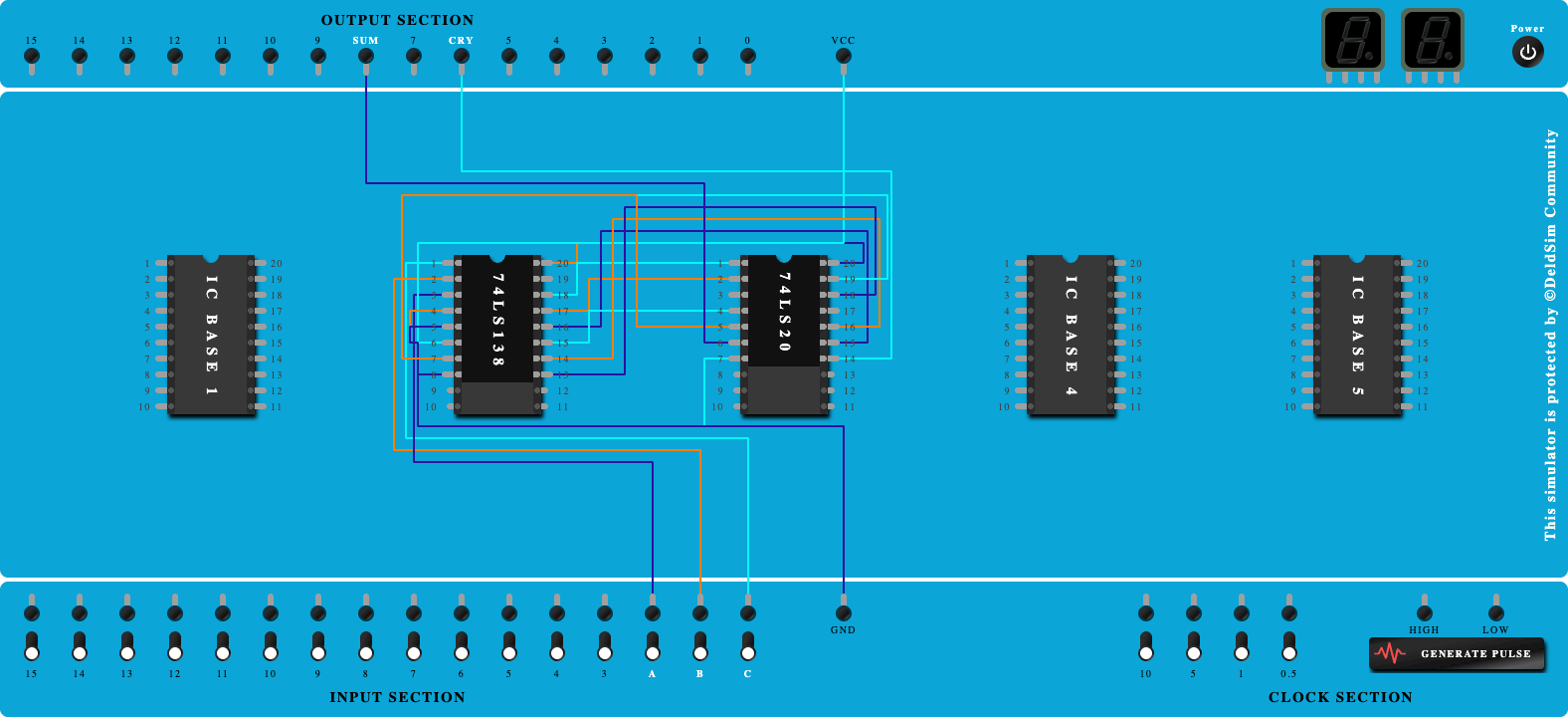
Full Adder function using 3:8 Decoder

To study and Verify the Full Adder function using 3:8 Decoder.
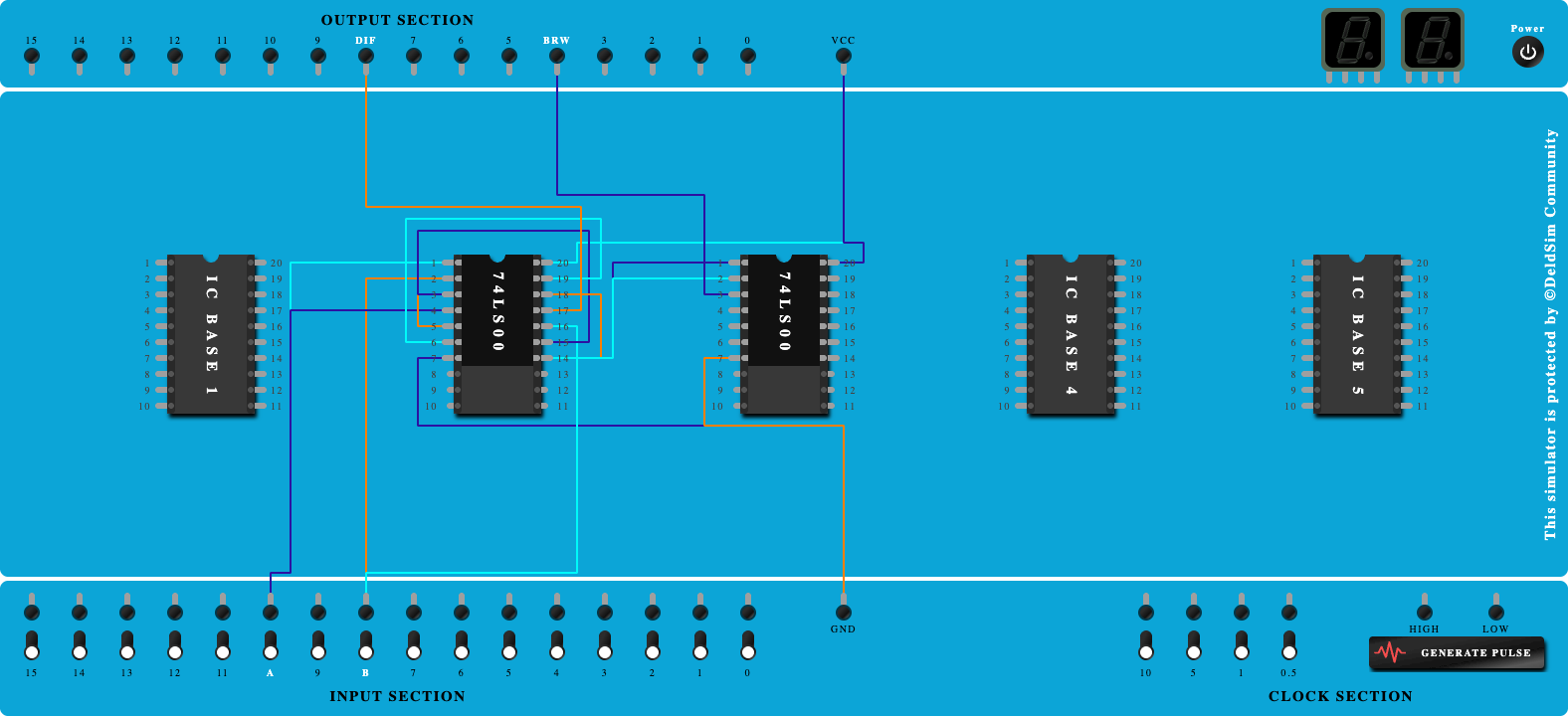
Half Subtracter Using NAND Gates
To study and verify the Half Subtracter using NAND Gates.
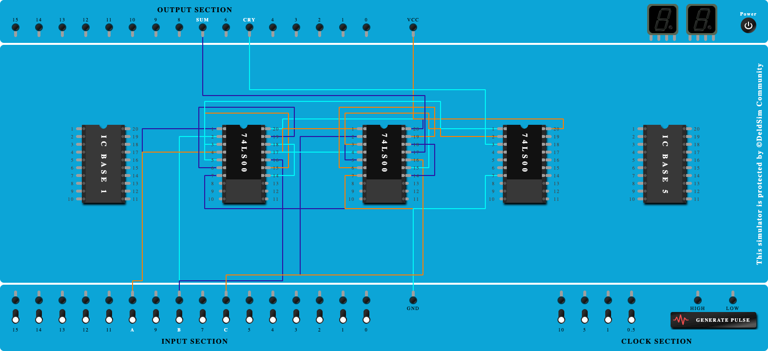
Full Adder Using NAND Gates
To study and verify the Full Adder using NAND Gates.
Half Adder using NAND Gates
To study and verify the Half Adder using NAND Gates.

Half subtractor using basic gates
To study and Verify the Half subtractor using basic gates.