Learning Objectives
- To understand the behavior and demonstrate the operation of BCD ripple counter using JK flip-flops.
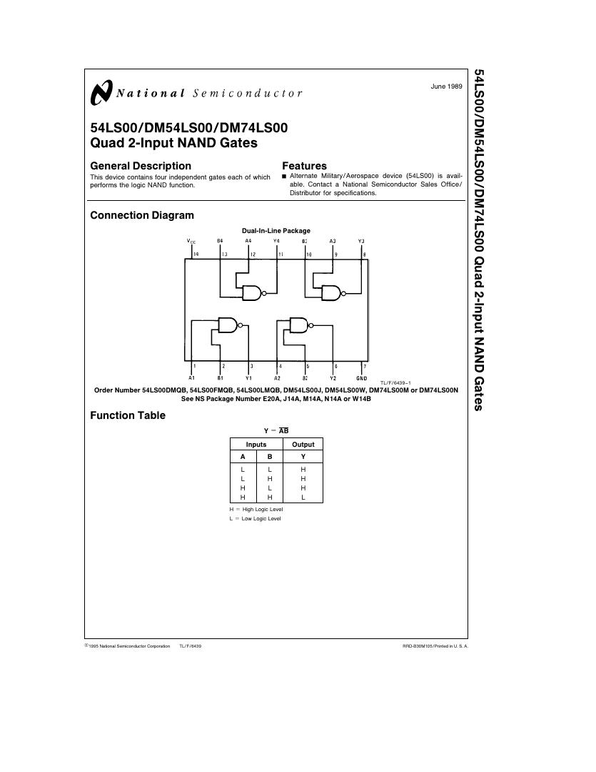
- To apply knowledge of the fundamental gates to create truth tables.
- To develop digital circuit building and troubleshooting skills.
- To understand key elements of TTL logic specification or datasheets.
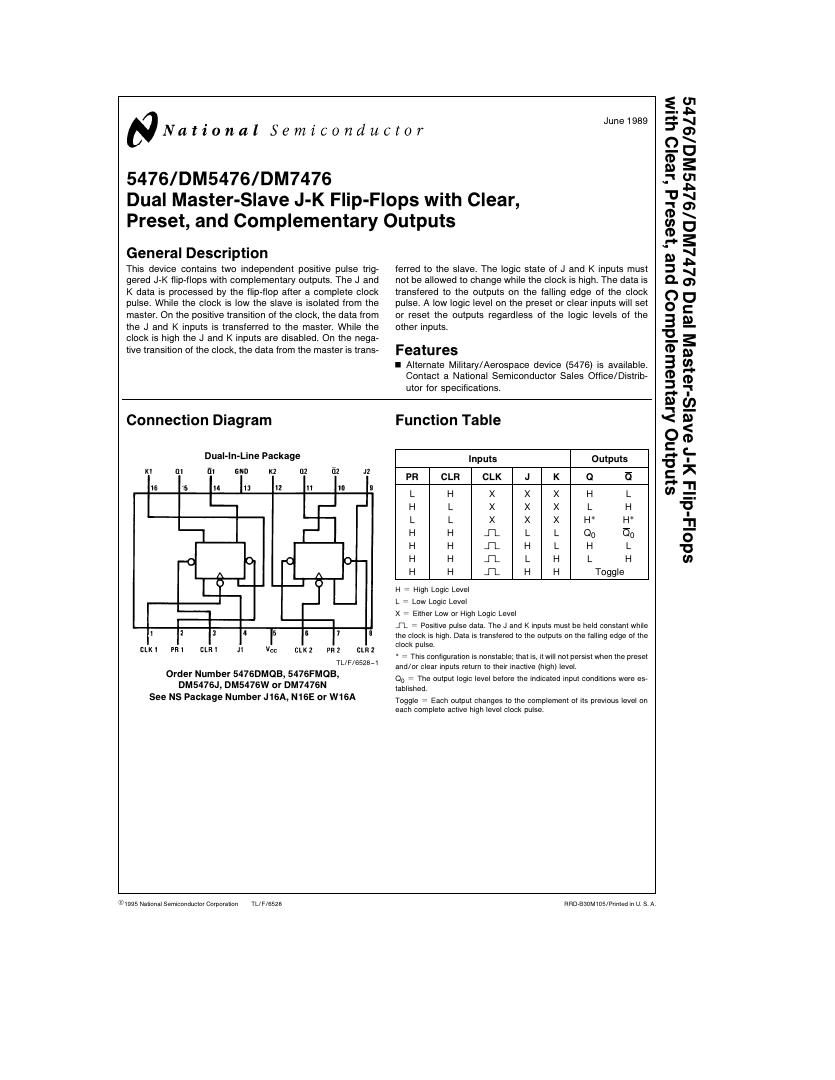
Integrated Circuits Used
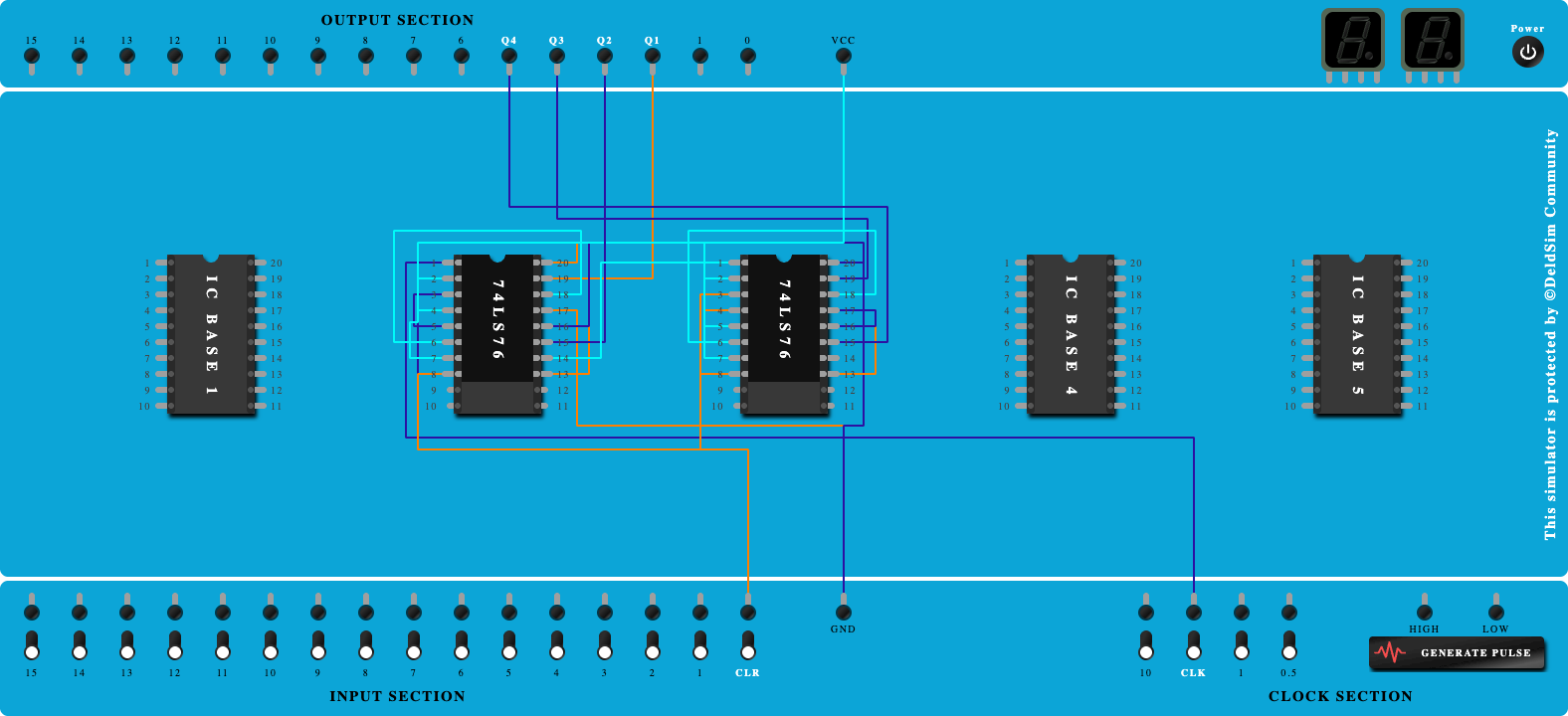
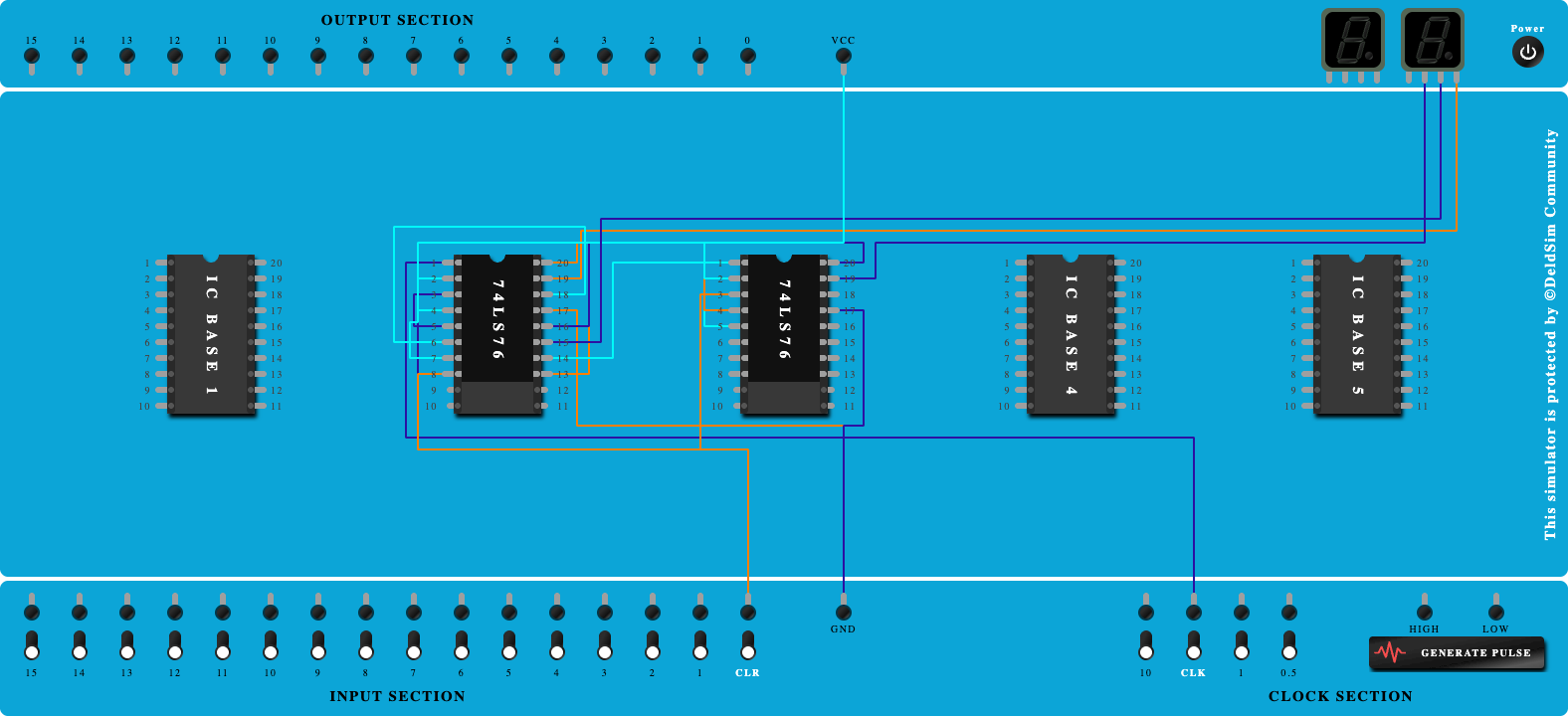
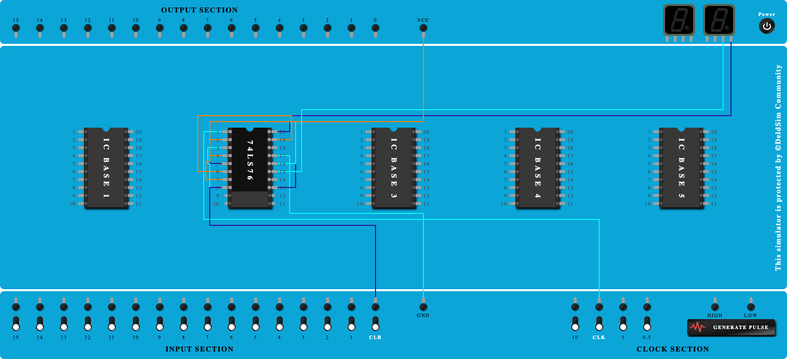
Circuit Tutorials
Procedure
- Place the IC on IC Trainer Kit.
- Connect VCC and ground to respective pins of IC Trainer Kit.
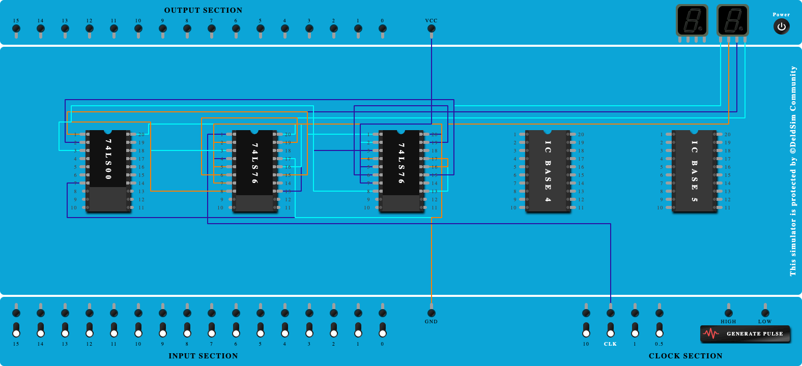
- Implement the circuit as shown in the circuit diagram.
- Connect the inputs to the input switches provided in the IC Trainer Kit.
- Connect the outputs to the switches of O/P LEDs
- Apply various combinations of inputs according to the truth table and observe the condition of LEDs.
- Note down the corresponding output readings for various combinations of inputs.
- Power Off Trainer Kit, disconnect all the wire connections and remove IC's from IC-Base.
Theory
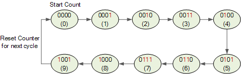
BCD Counter - Digital counters count upwards from zero to some pre-determined count value on the application of a clock signal. Once the count value is reached, resetting them returns the counter back to zero to start again.
A counter which resets after ten counts with a divide-by-10 count sequence from binary 0000 (decimal “0”) through to 1001 (decimal “9”) is called a “binary-coded-decimal counter” or BCD Counter for short and a MOD-10 counter can be constructed using a minimum of four toggle flip-flops. BCD Counter is a devices that goes through a sequence of ten states when it is clocked and returns to 0 after the count of 9.BCD Counter is a devices that goes through a sequence of ten states when it is clocked and returns to 0 after the count of 9.
A BCD counter counts in a sequence of ten and then returns back to zero after the count of nine. Obviously to count up to a binary value of nine, the counter must have at least four flip-flops within its chain to represent each decimal digit. It is called a BCDcounter because its ten state sequence is that of a BCD code and does not have a regular pattern, unlike a straight binary counter.
BCD Counter State Diagram
A decade counter has four flip-flops and 16 potential states, of which only 10 are used and if we connected a series of counters together we could count to 100 or 1,000 or to whatever final count number we choose.
BCD counters follow a sequence of ten states and count using BCD numbers from 0000 to 1001 and then returns to 0000 and repeats. Such a counter must have at least four flip-flops to represent each decimal digit, since a decimal digit is represented by a binary code with at least four bits giving a MOD-10 count.
Block Diagram

Precautions
- Make the connections according to the IC pin diagram.
- The connections should be tight on trainer kit.
- The Vcc and ground should be applied carefully at the specified pin only.
Conclusion
Related Study Materials
4-Bit Down Counter

To study and Verify the 4-Bit Down Counter.
3-Bit Down Counter
To study and Verify the 3-Bit Down Counter.

4-Bit Up Counter
To study and Verify the 4-Bit Up Counter.
2-Bit Up Counter
To study and Verify the 2-Bit Up Counter.

2-Bit Down Counter
To study and Verify the 2-Bit Down Counter.