Learning Objectives
- To understand the behavior and demonstrate the operation of 2-Input Ex-OR Gate.
- To apply knowledge of the fundamental gates to create truth tables.
- To develop digital circuit building and troubleshooting skills.
- To understand key elements of TTL logic specification or datasheets.
Integrated Circuits Used
Circuit Tutorials

Procedure
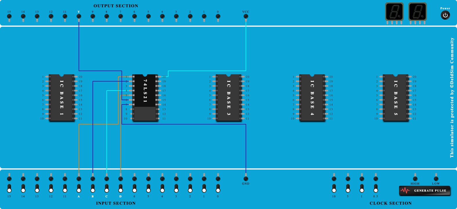
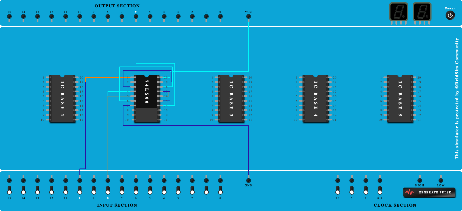
- Place the IC on IC Trainer Kit.
- Connect VCC and ground to respective pins of IC Trainer Kit.
- Implement the circuit as shown in the circuit diagram.
- Connect the inputs to the input switches provided in the IC Trainer Kit.
- Connect the outputs to the switches of O/P LEDs
- Apply various combinations of inputs according to the truth table and observe the condition of LEDs.
- Note down the corresponding output readings for various combinations of inputs.
- Power Off Trainer Kit, disconnect all the wire connections and remove IC's from IC-Base.
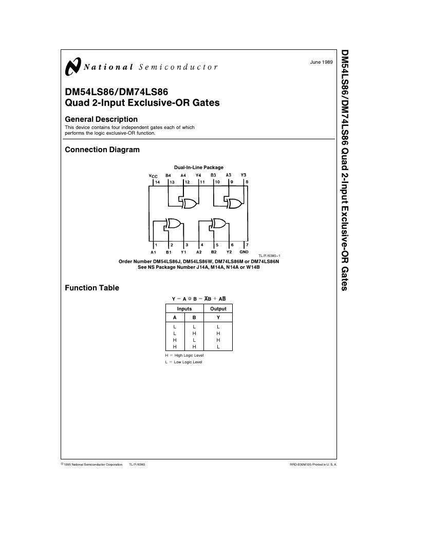
Theory
Ex-OR GATE - The full form of Ex-OR gate is Exclusive-OR gate. Its function is the same as that of OR gate except for some cases, when the inputs having an even number of ones.
In other words, the output of an Exclusive-OR gate ONLY goes “HIGH” when its two input terminals are at “DIFFERENT” logic levels with respect to each other. The Exclusive-OR Gate function, or Ex-OR for short, is achieved by combining standard logic gates together to form more complex gate functions that are used extensively in building arithmetic logic circuits, computational logic comparators and error detection circuits.
The two-input “Exclusive-OR” gate is basically a modulo two adder, since it gives the sum of two binary numbers.
Boolean Expression Y = A.B' + 'A.B = (A ⊕ B)
"If inputs having an odd number of ones, then Y is true"

Ex-OR gate operation is similar to that of OR gate, except for a few combinations of inputs. The output of Ex-OR gate is ‘1’ when an odd number of ones present at the inputs. Hence, the output of Ex-OR gate is also called as an odd function.
Block Diagram

Precautions
- Make the connections according to the IC pin diagram.
- The connections should be tight on trainer kit.
- The Vcc and ground should be applied carefully at the specified pin only.
Conclusion
Related Study Materials

2-Input AND Gate

To study and verify the truth table of 2-Input AND Gate.
Dual 4-Input AND Gates
To study and verify the truth table of Dual 4-Input AND Gates

2-Input NOR Gate
To study and verify the truth table of 2-Input NOR Gate.

Implementation of OR Gate using NOR gate
To study and verify the Implementation of OR Gate using NOR gate.
Implementation of NOR Gate using NAND gate
To study and verify the Implementation of NOR Gate using NAND gate.