
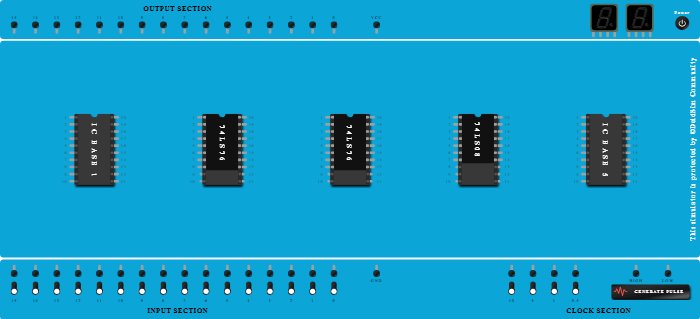
Integrated Circuits Used
Description
Pin no. 0, 1 = LOGIC-1. Pin no. 3=X. Pin no. 8 =Z, Output. Clock=low at pulse. Turn both logic-1 switches ON & X=1/ON and generate pulse & turn X=0/OFF and generate pulse & turn X=1/ON and generate pulse, then Z=1/ON. Since X=101 at Z=1, after 101 only Z becomes 1 else Z=0. If X=10001 then Z=0;
Procedure
- Add IC 74LS76 into ICBase-2 (74LS76).
- Add IC 74LS76 into ICBase-3 (74LS76).
- Add IC 74LS08 into ICBase-4 (74LS08).