
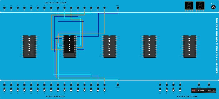
Integrated Circuits Used
Procedure
- Add IC 74LS139 into ICBase-2 (74LS139).
- Connect Pin-20 (VCC) of ICBase-2 (74LS139) to VCC Port.
- Connect Pin-7 (Output) of ICBase-2 (74LS139) to GND Port.
- Connect Pin-1 (Input) of ICBase-2 (74LS139) to Input-0.
- Connect Pin-2 (Input) of ICBase-2 (74LS139) to Input-1.
- Connect Pin-3 (Input) of ICBase-2 (74LS139) to Input-2.
- Connect Output-0 to Pin-4 (Output) of ICBase-2 (74LS139).
- Connect Output-1 to Pin-5 (Output) of ICBase-2 (74LS139).
- Connect Pin-6 (Output) of ICBase-2 (74LS139) to Output-2.
- Connect Pin-7 (Output) of ICBase-2 (74LS139) to Output-3.
- Connect Pin-8 (Ground) of ICBase-2 (74LS139) to Output-4.
- Connect Pin-16 (Output) of ICBase-2 (74LS139) to Output-6.
- Connect Pin-15 (Output) of ICBase-2 (74LS139) to Output-5.
- Connect Pin-14 (Output) of ICBase-2 (74LS139) to Output-7.