
Integrated Circuits Used
Description
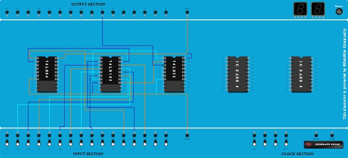
This circuit implements an 8:1 multiplexer using the 74153 IC. Inputs D0–D7 are controlled via switches, and select lines S0–S2 determine the active input. The output is monitored using an LED. The setup includes power and ground connections, and is designed for lab verification of multiplexing logic.
Procedure
- Add IC 74LS153 into ICBase-2 (74LS153).
- Add IC 74LS32 into ICBase-3 (74LS32).
- Connect GND Port to Pin-8 (Ground) of ICBase-2 (74LS153).
- Connect GND Port to Pin-7 (Ground) of ICBase-3 (74LS32).
- Connect GND Port to Pin-7 (Ground) of ICBase-1 (74LS04).
- Connect VCC Port to Pin-20 (VCC) of ICBase-3 (74LS32).
- Connect VCC Port to Pin-20 (VCC) of ICBase-2 (74LS153).
- Connect VCC Port to Pin-20 (VCC) of ICBase-1 (74LS04).
- Add IC 74LS04 into ICBase-1 (74LS04).
- Connect Pin-6 (Input) of ICBase-2 (74LS153) to Input-7.
- Connect Pin-5 (Input) of ICBase-2 (74LS153) to Input-8.
- Connect Pin-4 (Input) of ICBase-2 (74LS153) to Input-9.
- Connect Pin-3 (Input) of ICBase-2 (74LS153) to Input-10.
- Connect Input-11 to Pin-14 (Input) of ICBase-2 (74LS153).
- Connect Input-12 to Pin-15 (Input) of ICBase-2 (74LS153).
- Connect Input-13 to Pin-16 (Input) of ICBase-2 (74LS153).
- Connect Input-14 to Pin-17 (Input) of ICBase-2 (74LS153).
- Connect Input-2 to Pin-18 (Input) of ICBase-2 (74LS153).
- Connect Input-3 to Pin-2 (Input) of ICBase-2 (74LS153).
- Connect Input-4 to Pin-1 (Input) of ICBase-2 (74LS153).
- Connect Input-4 to Pin-1 (Input) of ICBase-1 (74LS04).
- Connect Pin-19 (Input) of ICBase-2 (74LS153) to Pin-2 (Output) of ICBase-1 (74LS04).
- Connect Pin-7 (Output) of ICBase-2 (74LS153) to Pin-1 (Input) of ICBase-3 (74LS32).
- Connect Pin-13 (Output) of ICBase-2 (74LS153) to Pin-2 (Input) of ICBase-3 (74LS32).
- Connect Output-6 to Pin-3 (Output) of ICBase-3 (74LS32).