
Integrated Circuits Used
Description
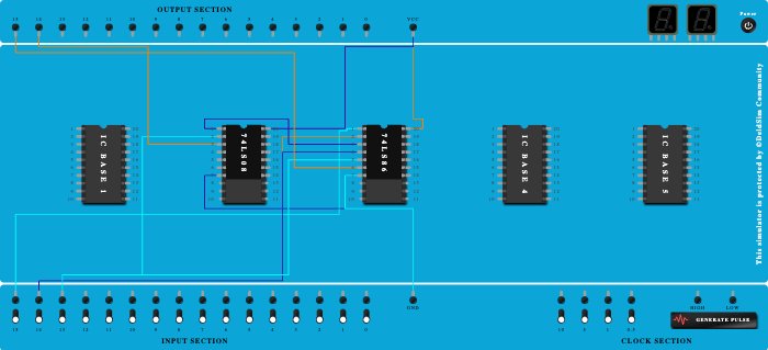
it is a circuit which adds a 2 bit number when the select input(the first input) is 0 and add the number when the select input is 1 . the outputs are o1 and o2 are sum and carry respectively for s=0 ; o1 and o2 are difference and borrow for s=1 .
Procedure
- Add IC 74LS08 into ICBase-2 (74LS08).
- Add IC 74LS86 into ICBase-3 (74LS86).
- Connect GND Port to Pin-7 (Ground) of ICBase-2 (74LS08).
- Connect Pin-7 (Ground) of ICBase-3 (74LS86) to GND Port.
- Connect VCC Port to Pin-20 (VCC) of ICBase-3 (74LS86).
- Connect Pin-20 (VCC) of ICBase-2 (74LS08) to VCC Port.
- Connect Input-15 to Pin-1 (Input) of ICBase-3 (74LS86).
- Connect Pin-2 (Input) of ICBase-3 (74LS86) to Input-14.
- Connect Pin-3 (Output) of ICBase-3 (74LS86) to Pin-1 (Input) of ICBase-2 (74LS08).
- Connect Pin-2 (Input) of ICBase-2 (74LS08) to Input-13.
- Connect Pin-3 (Output) of ICBase-2 (74LS08) to Output-14.
- Connect Pin-4 (Input) of ICBase-3 (74LS86) to Input-14.
- Connect Pin-5 (Input) of ICBase-3 (74LS86) to Input-13.
- Connect Pin-6 (Output) of ICBase-3 (74LS86) to Output-15.
- Connect GND Port to ICBase-3 (74LS86).
- Connect VCC Port to ICBase-2 (74LS08).
- Connect Pin-1 (Input) of ICBase-2 (74LS08) to ICBase-3 (74LS86).
- Connect Output-14 to ICBase-2 (74LS08).
- Connect Input-14 to ICBase-3 (74LS86).
- Connect Input-13 to ICBase-3 (74LS86).
- Connect Output-15 to ICBase-3 (74LS86).