
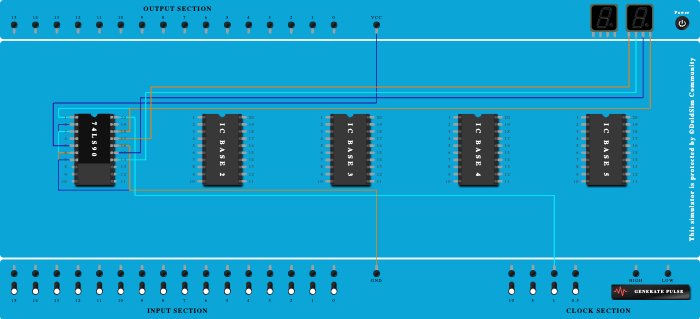
Integrated Circuits Used
Description
I this R0,R0,R9,R9 are the GND(only in Mod10). Take the INput (A) From the clock and Give the Qutput QA to Second input B. Take the QA as the LSB, and others are also similar. NC-(not connected to anywhere in any circut)
Procedure
- Add IC 74LS90 into ICBase-1 (74LS90).
- Connect GND Port to Pin-2 (Input) of ICBase-1 (74LS90).
- Connect GND Port to Pin-3 (Input) of ICBase-1 (74LS90).
- Connect GND Port to Pin-6 (Input) of ICBase-1 (74LS90).
- Connect GND Port to Pin-7 (Input) of ICBase-1 (74LS90).
- Connect Pin-1 (Input) of ICBase-1 (74LS90) to Pin-18 (Output) of ICBase-1 (74LS90).
- Connect GND Port to Pin-16 (Ground) of ICBase-1 (74LS90).
- Connect VCC Port to Pin-5 (VCC) of ICBase-1 (74LS90).
- Connect Clock port of 1Hz frequency to Pin-20 (Input) of ICBase-1 (74LS90).
- Connect Seven segment display 1 to Pin-18 (Output) of ICBase-1 (74LS90).
- Connect Seven segment display 1 to Pin-15 (Output) of ICBase-1 (74LS90).
- Connect Seven segment display 1 to Pin-14 (Output) of ICBase-1 (74LS90).
- Connect Seven segment display 1 to Pin-17 (Output) of ICBase-1 (74LS90).