
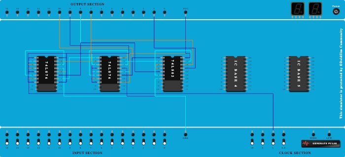
Integrated Circuits Used
Description
Design a digital system manage car parking system having capacity of 16 parking lots. Initial available space is to be shown as 15. After each car enters in a parking, count should be decremented by one. After parking of all 16 cars count should go to zero and an indication of parking full is to be given. Comment on the advantages and limitations of the circuit designed. Mention any other solution available for the same problem. (Hint: Use asynchronous counter) 1 will indicate when there are 0 spaces left.
Procedure
- Connect Clock port of 1Hz frequency to Pin-1 (Input) of ICBase-1 (74LS76).
- Connect VCC Port to Pin-2 (Input) of ICBase-1 (74LS76).
- Connect VCC Port to Pin-4 (Input) of ICBase-1 (74LS76).
- Connect VCC Port to Pin-5 (VCC) of ICBase-1 (74LS76).
- Connect Pin-6 (Input) of ICBase-1 (74LS76) to Pin-18 (Output) of ICBase-1 (74LS76).
- Connect VCC Port to Pin-7 (Input) of ICBase-1 (74LS76).
- Connect VCC Port to Pin-20 (Input) of ICBase-1 (74LS76).
- Connect GND Port to Pin-17 (Ground) of ICBase-1 (74LS76).
- Connect VCC Port to Pin-16 (Input) of ICBase-1 (74LS76).
- Connect VCC Port to Pin-13 (Input) of ICBase-1 (74LS76).
- Connect Pin-1 (Input) of ICBase-2 (74LS76) to Pin-14 (Output) of ICBase-1 (74LS76).
- Connect VCC Port to Pin-2 (Input) of ICBase-2 (74LS76).
- Connect VCC Port to Pin-4 (Input) of ICBase-2 (74LS76).
- Connect VCC Port to Pin-5 (VCC) of ICBase-2 (74LS76).
- Connect VCC Port to Pin-20 (Input) of ICBase-2 (74LS76).
- Connect GND Port to Pin-17 (Ground) of ICBase-2 (74LS76).
- Connect Pin-6 (Input) of ICBase-2 (74LS76) to Pin-18 (Output) of ICBase-2 (74LS76).
- Connect VCC Port to Pin-7 (Input) of ICBase-2 (74LS76).
- Connect VCC Port to Pin-8 (Input) of ICBase-2 (74LS76).
- Connect VCC Port to Pin-3 (Input) of ICBase-2 (74LS76).
- Connect VCC Port to Pin-3 (Input) of ICBase-1 (74LS76).
- Connect VCC Port to Pin-8 (Input) of ICBase-1 (74LS76).
- Connect VCC Port to Pin-16 (Input) of ICBase-2 (74LS76).
- Connect VCC Port to Pin-13 (Input) of ICBase-2 (74LS76).
- Connect VCC Port to Pin-20 (VCC) of ICBase-3 (74LS02).
- Connect GND Port to Pin-7 (Ground) of ICBase-3 (74LS02).
- Connect Output-10 to Pin-15 (Output) of ICBase-2 (74LS76).
- Connect Output-9 to Pin-19 (Output) of ICBase-2 (74LS76).
- Connect Output-8 to Pin-15 (Output) of ICBase-1 (74LS76).
- Connect Output-7 to Pin-19 (Output) of ICBase-1 (74LS76).
- Connect Pin-1 (Output) of ICBase-3 (74LS02) to Pin-15 (Output) of ICBase-2 (74LS76).
- Connect Pin-2 (Input) of ICBase-3 (74LS02) to Pin-19 (Output) of ICBase-2 (74LS76).
- Connect Pin-4 (Output) of ICBase-3 (74LS02) to Pin-3 (Input) of ICBase-3 (74LS02).
- Connect Pin-5 (Input) of ICBase-3 (74LS02) to Pin-15 (Output) of ICBase-1 (74LS76).
- Connect Pin-19 (Output) of ICBase-3 (74LS02) to Pin-6 (Input) of ICBase-3 (74LS02).
- Connect Pin-18 (Input) of ICBase-3 (74LS02) to Pin-19 (Output) of ICBase-1 (74LS76).
- Connect Output-1 to Pin-17 (Input) of ICBase-3 (74LS02).
- Add IC 74LS76 into ICBase-2 (74LS76).
- Add IC 74LS02 into ICBase-3 (74LS02).
- Add IC 74LS76 into ICBase-1 (74LS76).