
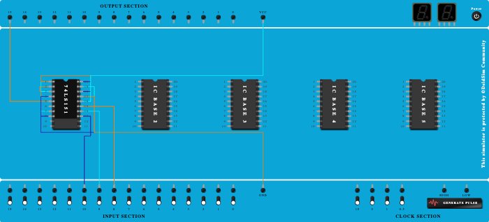
Integrated Circuits Used
Description
//for m(1,3,5,7) 1.Connect VCC and ground , strobe ... 2.Connect I1,I3,I5 and I7 to Vcc. 3.Remaining inputs to be connected to GRD. 4.Connect selectors ABC. //Verification 1.Output should be HIGH iff selector combination is (binary) 001 , 011 , 101 and 111. In all other cases , Output should be LOW.
Procedure
- Add IC 74LS151 into ICBase-1 (74LS151).
- Connect GND Port to Pin-8 (Ground) of ICBase-1 (74LS151).
- Connect GND Port to Pin-7 (Input) of ICBase-1 (74LS151).
- Connect Output-15 to Pin-5 (Output) of ICBase-1 (74LS151).
- Connect VCC Port to Pin-20 (VCC) of ICBase-1 (74LS151).
- Connect VCC Port to Pin-3 (Input) of ICBase-1 (74LS151).
- Connect VCC Port to Pin-1 (Input) of ICBase-1 (74LS151).
- Connect VCC Port to Pin-18 (Input) of ICBase-1 (74LS151).
- Connect VCC Port to Pin-16 (Input) of ICBase-1 (74LS151).
- Connect GND Port to Pin-2 (Input) of ICBase-1 (74LS151).
- Connect GND Port to Pin-4 (Input) of ICBase-1 (74LS151).
- Connect GND Port to Pin-19 (Input) of ICBase-1 (74LS151).
- Connect GND Port to Pin-17 (Input) of ICBase-1 (74LS151).
- Connect Input-10 to Pin-13 (Input) of ICBase-1 (74LS151).
- Connect Input-9 to Pin-14 (Input) of ICBase-1 (74LS151).
- Connect Input-8 to Pin-15 (Input) of ICBase-1 (74LS151).