
Integrated Circuits Used
Description
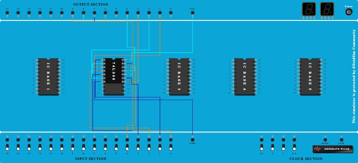
4 low light bulbs will glow only at night and 4 High light bulbs will glow at night when some movement is detected by PIR sensor. In this we use IC-7408 7408 IC is a QUAD 2-Input AND GATES and contains four independent gates each of which performs the logic AND function. INPUT SECTION Pin 0 - LDR sensor (gives output 1 at night) Pin 1 - PIR sensor of first room (gives output 1 when some motion is detected in room 1) Pin 2 - PIR sensor of second room (gives output 1 when some motion is detected in room 2) Pin 3 - PIR sensor of third room (gives output 1 when some motion is detected in room 3) Pin 4 - PIR sensor of fourth room (gives output 1 when some motion is detected in room 4) OUTPUT SECTION - PIN 1 - High light of room 1 PIN 2 - High light of room 2 PIN 3 - High light of room 3 PIN 4 - High light of room 4 PIN 6 - Low light of room 1 PIN 7 - Low light of room 2 PIN 8 - Low light of room 3 PIN 9 - Low light of room 4
Procedure
- Add IC 74LS08 into ICBase-2 (74LS08).
- Connect Input-1 to Pin-1 (Input) of ICBase-2 (74LS08).
- Connect Pin-2 (Input) of ICBase-2 (74LS08) to Input-0.
- Connect Output-1 to Pin-3 (Output) of ICBase-2 (74LS08).
- Connect GND Port to Pin-7 (Ground) of ICBase-2 (74LS08).
- Connect VCC Port to Pin-20 (VCC) of ICBase-2 (74LS08).
- Connect Pin-4 (Input) of ICBase-2 (74LS08) to Input-2.
- Connect Pin-5 (Input) of ICBase-2 (74LS08) to Input-0.
- Connect Output-2 to Pin-6 (Output) of ICBase-2 (74LS08).
- Connect Output-3 to Pin-14 (Output) of ICBase-2 (74LS08).
- Connect Input-3 to Pin-15 (Input) of ICBase-2 (74LS08).
- Connect Input-0 to Pin-16 (Input) of ICBase-2 (74LS08).
- Connect Pin-18 (Input) of ICBase-2 (74LS08) to Input-4.
- Connect Input-0 to Pin-19 (Input) of ICBase-2 (74LS08).
- Connect Output-4 to Pin-17 (Output) of ICBase-2 (74LS08).
- Connect Input-0 to Output-6.
- Connect Output-7 to Input-0.
- Connect Output-8 to Input-0.
- Connect Output-9 to Input-0.