
Integrated Circuits Used
Description
This device contains four independent gates each of which performs the logic NAND function. The open-collector outputs require external pull-up resistors for proper logical operation.
Procedure
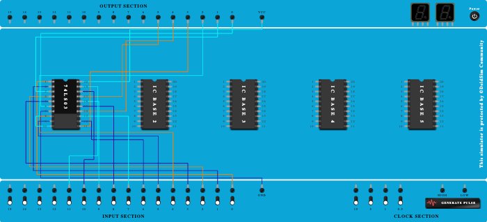
- Connect Pin-7 (Ground) of ICBase-1 (74LS03) to GND Port.
- Add IC 74LS03 into ICBase-1 (74LS03).
- Connect Pin-20 (VCC) of ICBase-1 (74LS03) to VCC Port.
- Connect Pin-1 (Input) of ICBase-1 (74LS03) to Input-0.
- Connect Pin-2 (Input) of ICBase-1 (74LS03) to Input-1.
- Connect Pin-3 (Output) of ICBase-1 (74LS03) to Output-0.
- Connect Pin-4 (Input) of ICBase-1 (74LS03) to Input-2.
- Connect Pin-5 (Input) of ICBase-1 (74LS03) to Input-3.
- Connect Pin-6 (Output) of ICBase-1 (74LS03) to Output-1.
- Connect Input-4 to Pin-8 (Input & Output) of ICBase-1 (74LS03).
- Connect Input-5 to Pin-9 (Input & Output) of ICBase-1 (74LS03).
- Connect Output-2 to Pin-10 (Input & Output) of ICBase-1 (74LS03).
- Connect Output-3 to Pin-11 (Input & Output) of ICBase-1 (74LS03).
- Connect Input-6 to Pin-12 (Input & Output) of ICBase-1 (74LS03).
- Connect Input-7 to Pin-13 (Input & Output) of ICBase-1 (74LS03).
- Connect Pin-14 (Output) of ICBase-1 (74LS03) to Output-4.
- Connect Pin-15 (Input) of ICBase-1 (74LS03) to Input-8.
- Connect Pin-16 (Input) of ICBase-1 (74LS03) to Input-9.
- Connect Pin-17 (Output) of ICBase-1 (74LS03) to Output-5.
- Connect Pin-18 (Input) of ICBase-1 (74LS03) to Input-10.
- Connect Pin-19 (Input) of ICBase-1 (74LS03) to Input-11.