
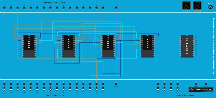
Integrated Circuits Used
Description
Question: Consider you want to create a kid’s playing box that have 3 input button each defined by a fix number. Like ✓ Button A – 1 ✓ Button B – 3 ✓ Button C – 5 ❖ Now if any combination of those buttons is turn on (1) and the addition of those corresponding button’s value is an even number then a green bulb will light on (1) else it will remain light off (0). ▪ Now Draw the Truth table for all possible 8 combinations ▪ Find the Boolean Expression of the Truth Table ▪ Try Simplify the Circuit using Boolean Algebra ▪ Draw the simplified circuit ▪ Create the Circuit in the DeldSim. ▪ Submit with Screenshot, Working and Deldsim Link
Procedure
- Add IC 74LS32 into ICBase-1 (74LS32).
- Add IC 74LS08 into ICBase-2 (74LS08).
- Add IC 74LS08 into ICBase-3 (74LS08).
- Add IC 74LS04 into ICBase-4 (74LS04).
- Connect VCC Port to Pin-20 (VCC) of ICBase-1 (74LS32).
- Connect VCC Port to Pin-20 (VCC) of ICBase-2 (74LS08).
- Connect VCC Port to Pin-20 (VCC) of ICBase-3 (74LS08).
- Connect VCC Port to Pin-20 (VCC) of ICBase-4 (74LS04).
- Connect GND Port to ICBase-1 (74LS32).
- Connect GND Port to Pin-7 (Ground) of ICBase-1 (74LS32).
- Connect GND Port to Pin-7 (Ground) of ICBase-2 (74LS08).
- Connect GND Port to ICBase-3 (74LS08).
- Connect GND Port to Pin-7 (Ground) of ICBase-3 (74LS08).
- Connect GND Port to Pin-7 (Ground) of ICBase-4 (74LS04).
- Connect Pin-1 (Input) of ICBase-1 (74LS32) to Pin-3 (Output) of ICBase-3 (74LS08).
- Connect Pin-3 (Input) of ICBase-4 (74LS04) to Input-1.
- Connect Pin-4 (Input) of ICBase-2 (74LS08) to Pin-4 (Output) of ICBase-4 (74LS04).
- Connect Input-0 to Pin-5 (Input) of ICBase-2 (74LS08).
- Connect Pin-4 (Input) of ICBase-3 (74LS08) to Pin-6 (Output) of ICBase-2 (74LS08).
- Connect Input-2 to Pin-5 (Input) of ICBase-3 (74LS08).
- Connect Pin-2 (Input) of ICBase-1 (74LS32) to Pin-6 (Output) of ICBase-3 (74LS08).
- Connect Pin-19 (Input) of ICBase-1 (74LS32) to Pin-3 (Output) of ICBase-1 (74LS32).
- Connect Pin-5 (Input) of ICBase-4 (74LS04) to Input-2.
- Connect Pin-19 (Input) of ICBase-2 (74LS08) to Pin-6 (Output) of ICBase-4 (74LS04).
- Connect Input-0 to Pin-18 (Input) of ICBase-2 (74LS08).
- Connect Pin-19 (Input) of ICBase-3 (74LS08) to Pin-17 (Output) of ICBase-2 (74LS08).
- Connect Input-1 to Pin-18 (Input) of ICBase-3 (74LS08).
- Connect Pin-18 (Input) of ICBase-1 (74LS32) to Pin-17 (Output) of ICBase-3 (74LS08).
- Connect Output-0 to Pin-17 (Output) of ICBase-1 (74LS32).
- Connect VCC Port to ICBase-1 (74LS32).
- Connect Pin-1 (Input) of ICBase-4 (74LS04) to Input-0.
- Connect Pin-1 (Input) of ICBase-2 (74LS08) to Pin-2 (Output) of ICBase-4 (74LS04).
- Connect Input-1 to Pin-2 (Input) of ICBase-2 (74LS08).
- Connect Pin-1 (Input) of ICBase-3 (74LS08) to Pin-3 (Output) of ICBase-2 (74LS08).
- Connect Input-2 to Pin-2 (Input) of ICBase-3 (74LS08).