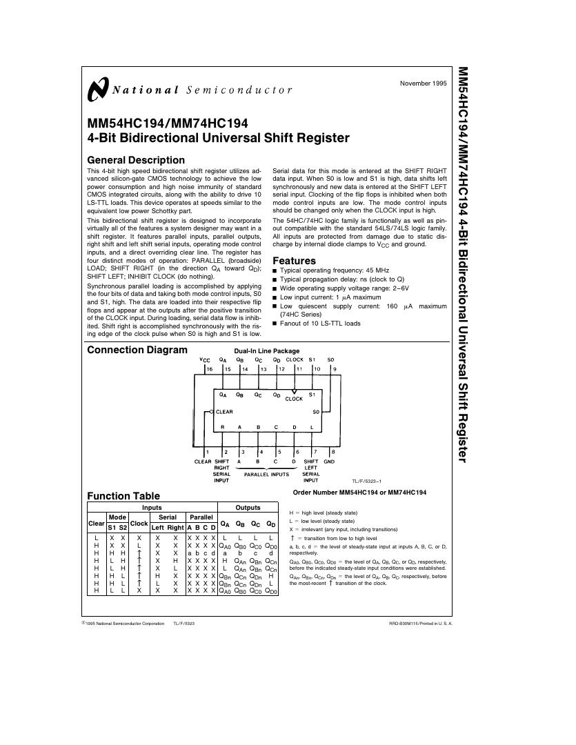
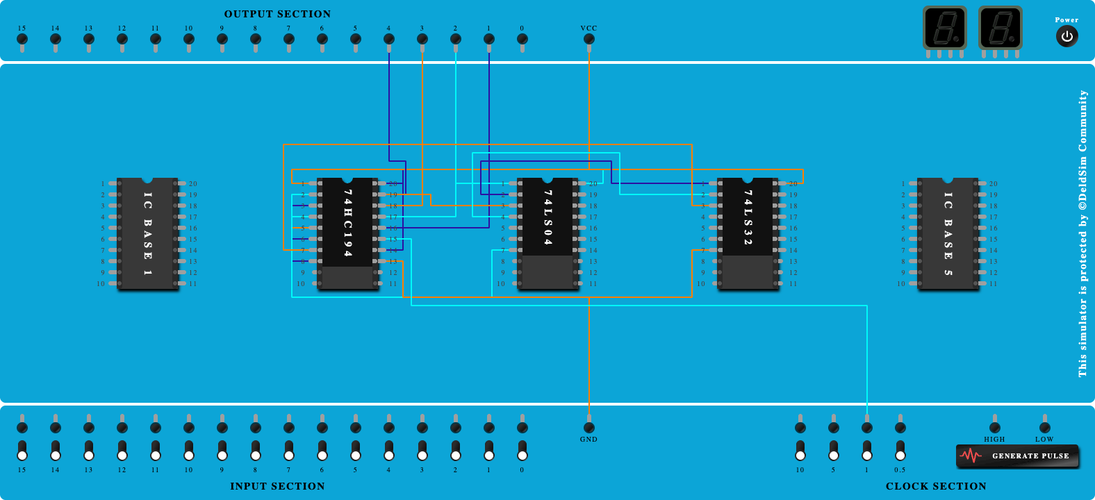
Design and implement pulse train generator using IC74HC194 for pulse 111001 (Use right shift)

100%
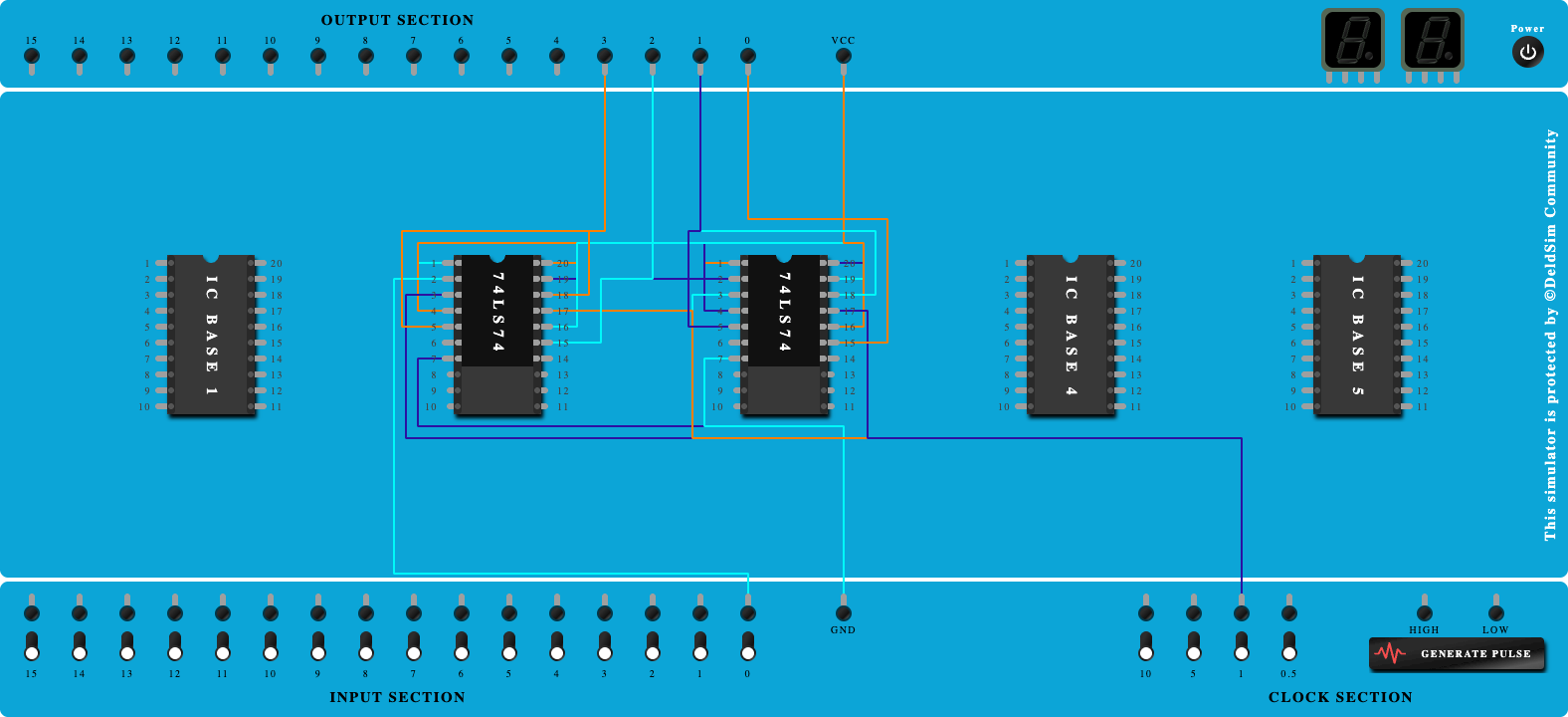
Step-by-Step Procedure
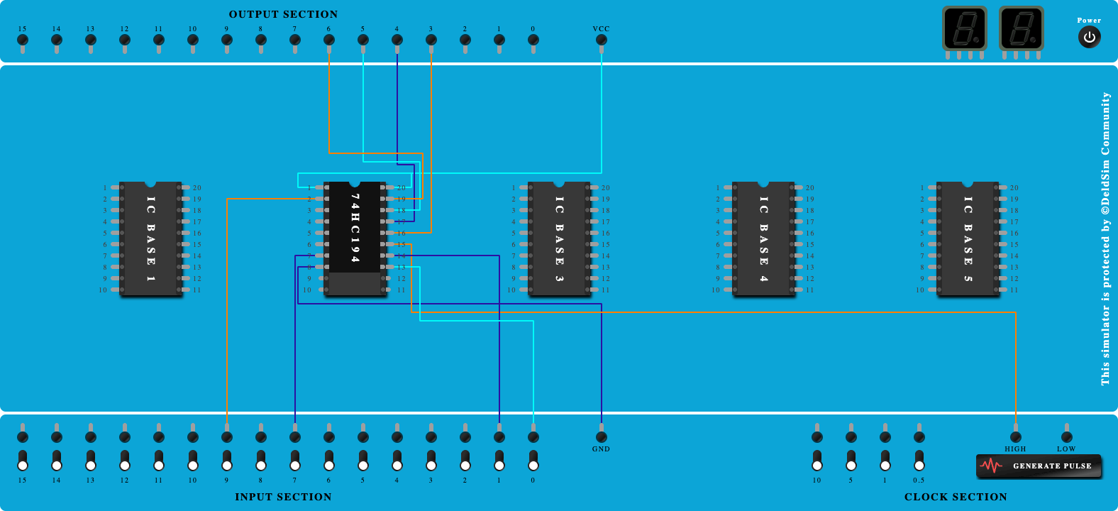
- Click on 'Next' button to Add IC-74HC194
- Click on 'Next' button to Connect GND and VCC of IC
- Click on 'Next' button to Connect Paraller Input D3-D0 to GND
- Click on 'Next' button to Connect DSL to GND
- Click on 'Next' button to Connect S1 to GND
- Click on 'Next' button to Connect S0 to Vcc
- Click on 'Next' button to Connect Clock pin to Clock port
- Click on 'Next' button to Connect Clear pin to Vcc
- Click on 'Next' button to Connect Output to output ports
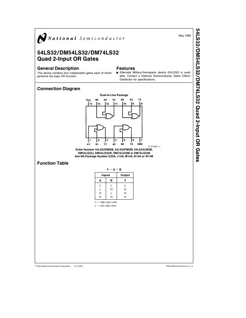
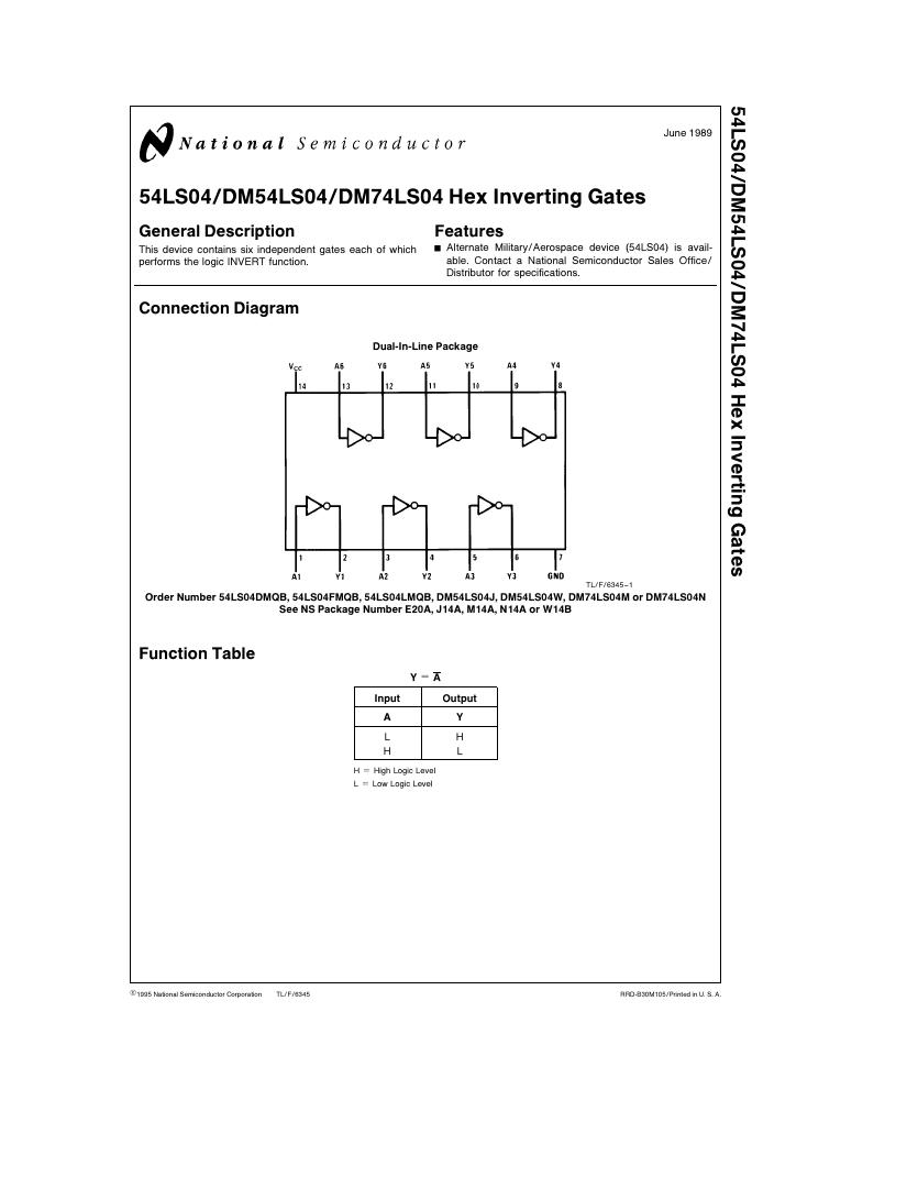
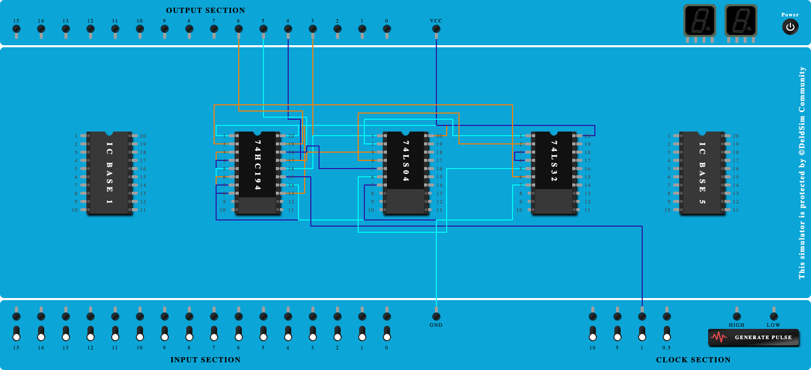
- Click on 'Next' button to add IC 74LS04 and 74LS32
- Click on 'Next' button to Connect GND and Vcc of both Ics
- Click on 'Next' button to connect output-4 to NOT Gate pin-1
- Click on 'Next' button to connect output-3 to NOT Gate pin-3
- Click on 'Next' button to connect output-2 to NOT Gate pin-5
- Click on 'Next' button to connect output-1 of NOT Gate to Input-1 of OR Gate
- Click on 'Next' button to connect output-2 of NOT Gate to Input-2 of OR Gate
- Click on 'Next' button to connect output-1 of OR Gate to Pin-4 of OR Gate
- Click on 'Next' button to connect output-3 of NOT Gate to Pin-5 of OR Gate
- Click on 'Next' button to connect output-2 of OR Gate to Pin-2 (DSR)