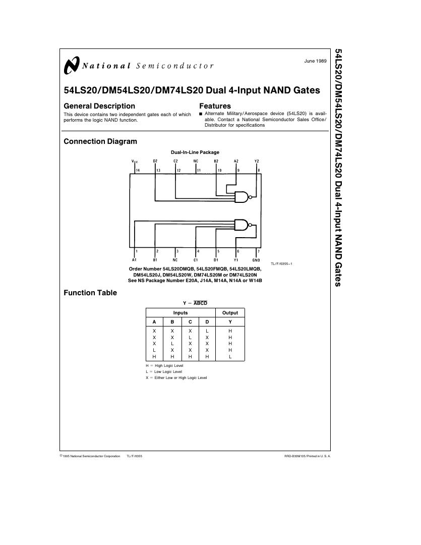
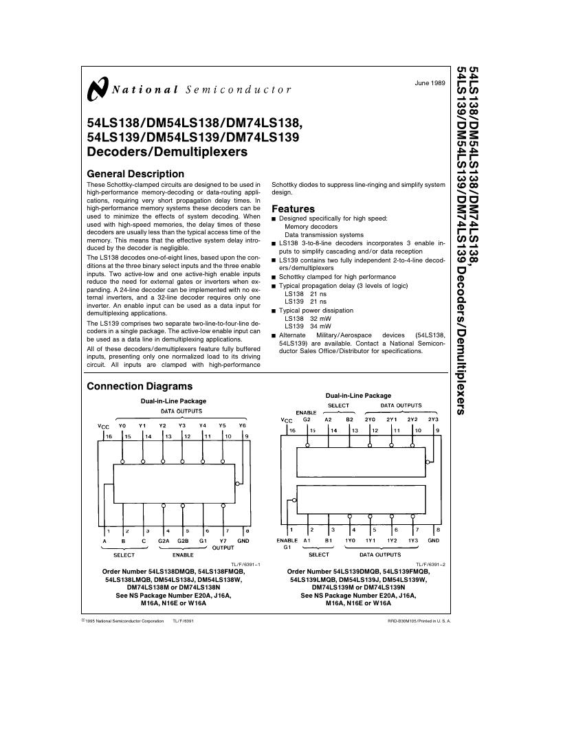
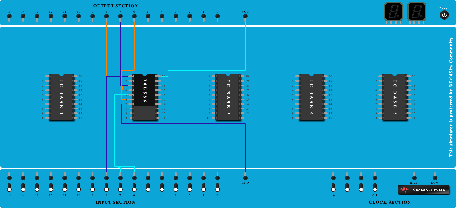
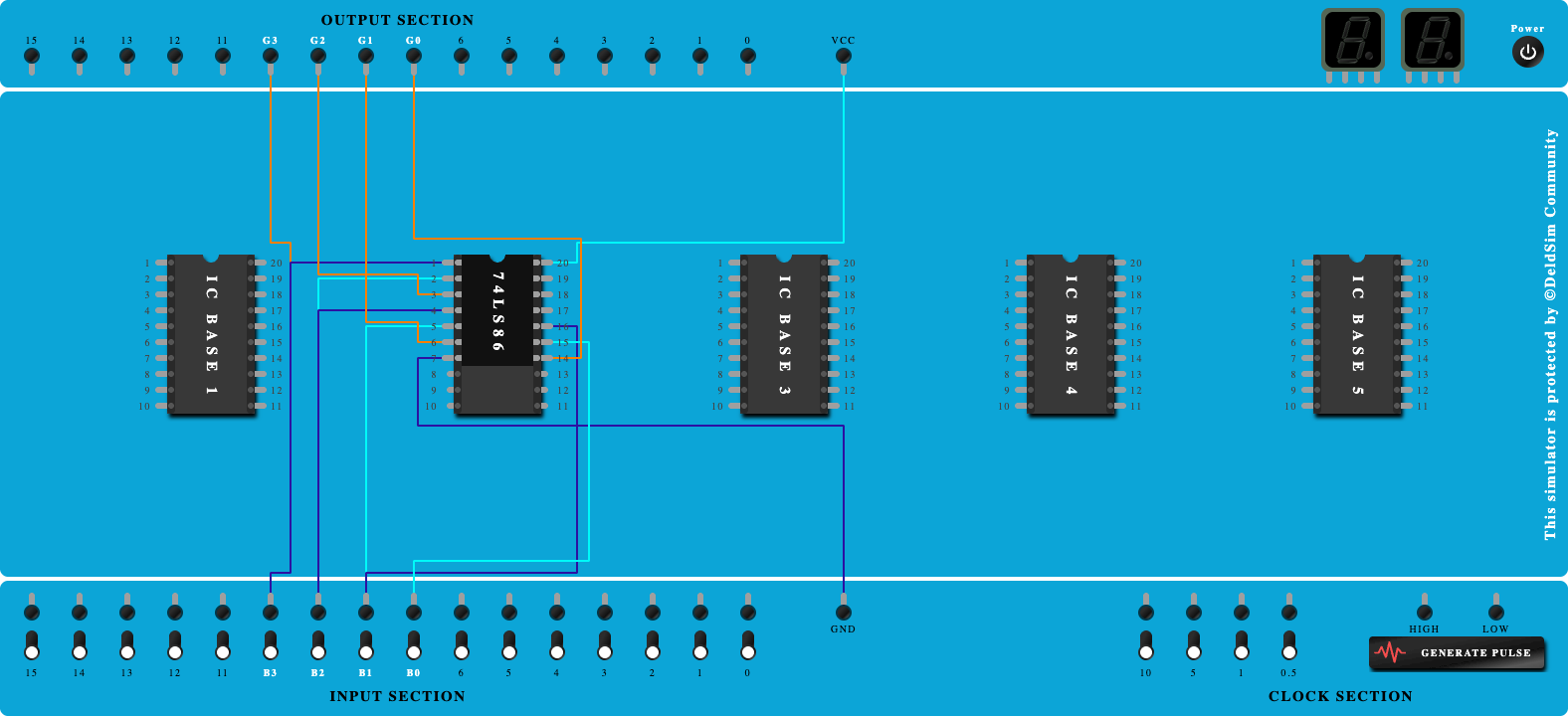
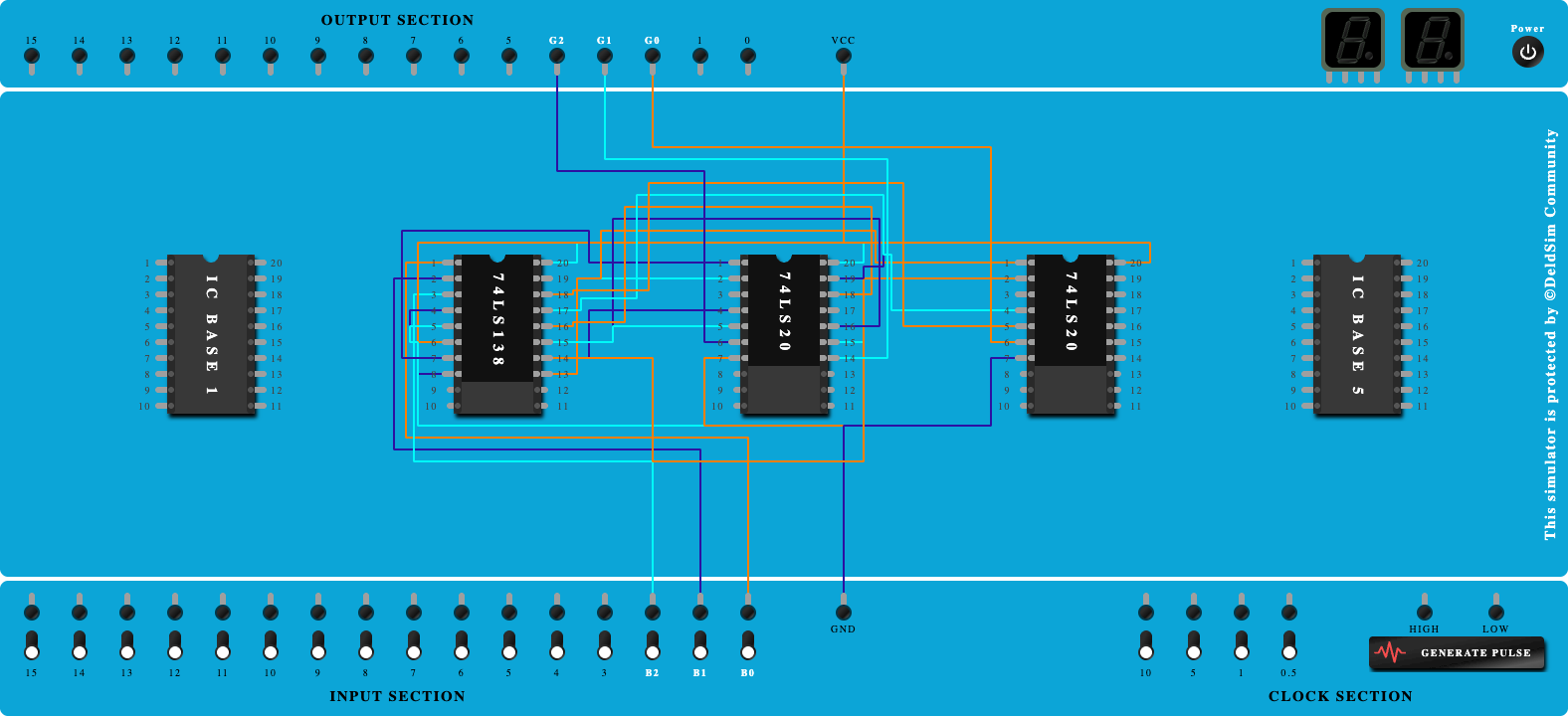
Design & Implement 3-bit Binary to Gray code converter using IC- 74LS138.

100%
Step-by-Step Procedure
- Click on 'Next' button to Add IC-74LS138
- Click on 'Next' button to Connect GND and VCC of IC
- Click on 'Next' button to Connect Input 'B0' to Select Line A
- Click on 'Next' button to Connect Input 'B1' to Select Line B
- Click on 'Next' button to Connect Input 'B2' to Select Line C
- Click on 'Next' button to Connect 'G1' to Vcc
- Click on 'Next' button to Connect 'G2A' and 'G2B' to GND
- Click on 'Next' button to Add IC-74LS20
- Click on 'Next' button to Connect GND and VCC of ICs
- Click on 'Next' button to Connect output 'Y7' to Pin-1 of 74LS20
- Click on 'Next' button to Connect output 'Y6' to Pin-2 of 74LS20
- Click on 'Next' button to Connect output 'Y6' to Pin-1 of 2nd 74LS20
- Click on 'Next' button to Connect output 'Y5' to Pin-4 and Pin-9 of 74LS20
- Click on 'Next' button to Connect output 'Y5' to Pin-2 of 2nd 74LS20
- Click on 'Next' button to Connect output 'Y4' to Pin-10 and Pin-5 of 74LS20
- Click on 'Next' button to Connect output 'Y3' to Pin-12 of 74LS20
- Click on 'Next' button to Connect output 'Y2' to Pin-13 of 74LS20
- Click on 'Next' button to Connect output 'Y2' to Pin-4 of 2nd 74LS20
- Click on 'Next' button to Connect output 'Y1' to Pin-5 of 2nd 74LS20
- Click on 'Next' button to Connect Pin-6 of 74LS20 to Output port as 'G2'
- Click on 'Next' button to Connect Pin-8 of 74LS20 to Output port as 'G1'
- Click on 'Next' button to Connect Pin-6 of 2nd 74LS20 to Output port as 'G0'