Learning Objectives
- To understand the behavior and demonstrate the Implementation of Multiplexer using gates.
- To apply knowledge of the fundamental gates to create truth tables.
- To develop digital circuit building and troubleshooting skills.
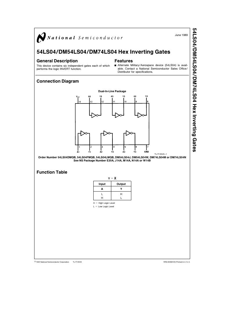
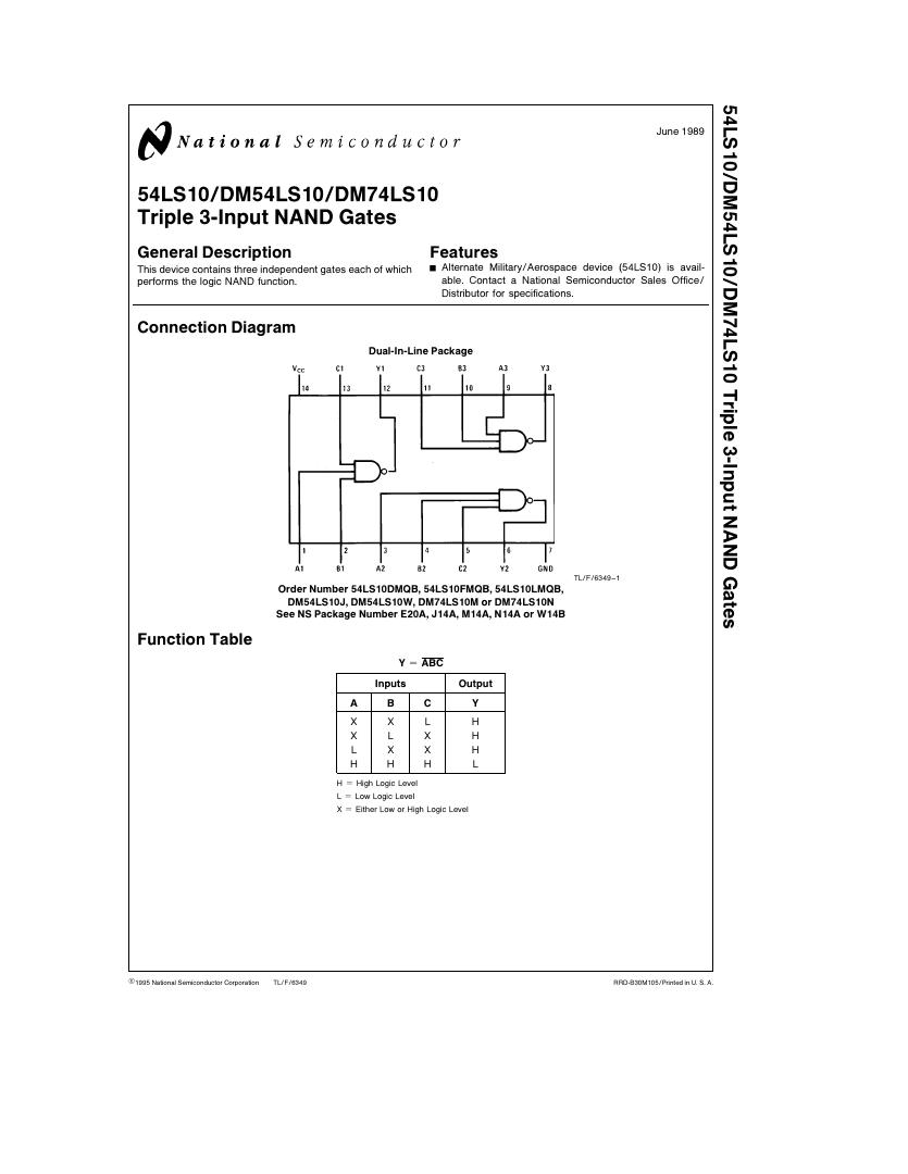
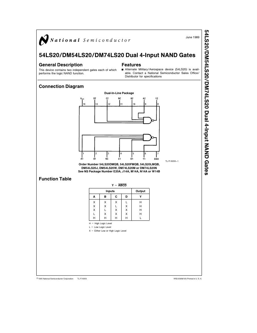
- To understand key elements of TTL logic specification or datasheets.
Integrated Circuits Used
Circuit Tutorials
Procedure
- Place the IC on IC Trainer Kit.
- Connect VCC and ground to respective pins of IC Trainer Kit.
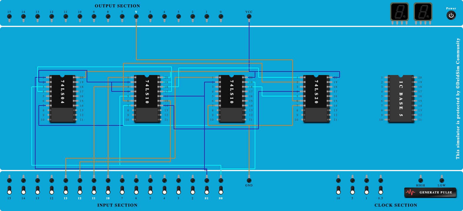
- Implement the circuit as shown in the circuit diagram.
- Connect the inputs to the input switches provided in the IC Trainer Kit.
- Connect the outputs to the switches of O/P LEDs
- Apply various combinations of inputs according to the truth table and observe the condition of LEDs.
- Note down the corresponding output readings for various combinations of inputs.
- Power Off Trainer Kit, disconnect all the wire connections and remove IC's from IC-Base.
Theory
Multiplexer - Multiplexing is the generic term used to describe the operation of sending one or more analogue or digital signals over a common transmission line at different times or speeds and as such, the device we use to do just that is called a Multiplexer.
The multiplexer , shortened to “MUX” or “MPX”, is a combinational logic circuit designed to switch one of several input lines through to a single common output line by the application of a control signal. Multiplexers operate like very fast acting multiple position rotary switches connecting or controlling multiple input lines called “channels” one at a time to the output. Multiplexers, or MUX’s, can be either digital circuits made from high speed logic gates used to switch digital or binary data or they can be analogue types using transistors, MOSFET’s or relays to switch one of the voltage or current inputs through to a single output.
Basic Multiplexing Switch
The rotary switch, also called a wafer switch as each layer of the switch is known as a wafer, is a mechanical device whose input is selected by rotating a shaft. In other words, the rotary switch is a manual switch that you can use to select individual data or signal lines simply by turning its inputs “ON” or “OFF”. So how can we select each data input automatically using a digital device.
In digital electronics, multiplexers are also known as data selectors because they can “select” each input line, are constructed from individual Analogue Switches encased in a single IC package as opposed to the “mechanical” type selectors such as normal conventional switches and relays.
They are used as one method of reducing the number of logic gates required in a circuit design or when a single data line or data bus is required to carry two or more different digital signals. For example, a single 8-channel multiplexer.
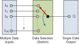
Generally, the selection of each input line in a multiplexer is controlled by an additional set of inputs called control lines and according to the binary condition of these control inputs, either “HIGH” or “LOW” the appropriate data input is connected directly to the output. Normally, a multiplexer has an even number of 2 n data input lines and a number of “control” inputs that correspond with the number of data inputs.
Block Diagram

Precautions
- Make the connections according to the IC pin diagram.
- The connections should be tight on trainer kit.
- The Vcc and ground should be applied carefully at the specified pin only.
Conclusion
Related Study Materials
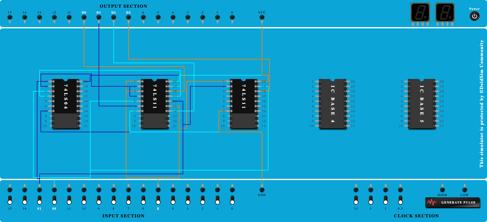
Design and implement De-Multiplexer using gates
To study , design and implement De-Multiplexer using gates.
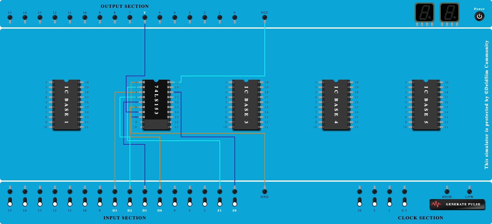
4:1 Multiplexer Using IC 74LS153
To study and Verify the 4:1 Multiplexer Using IC 74LS153.
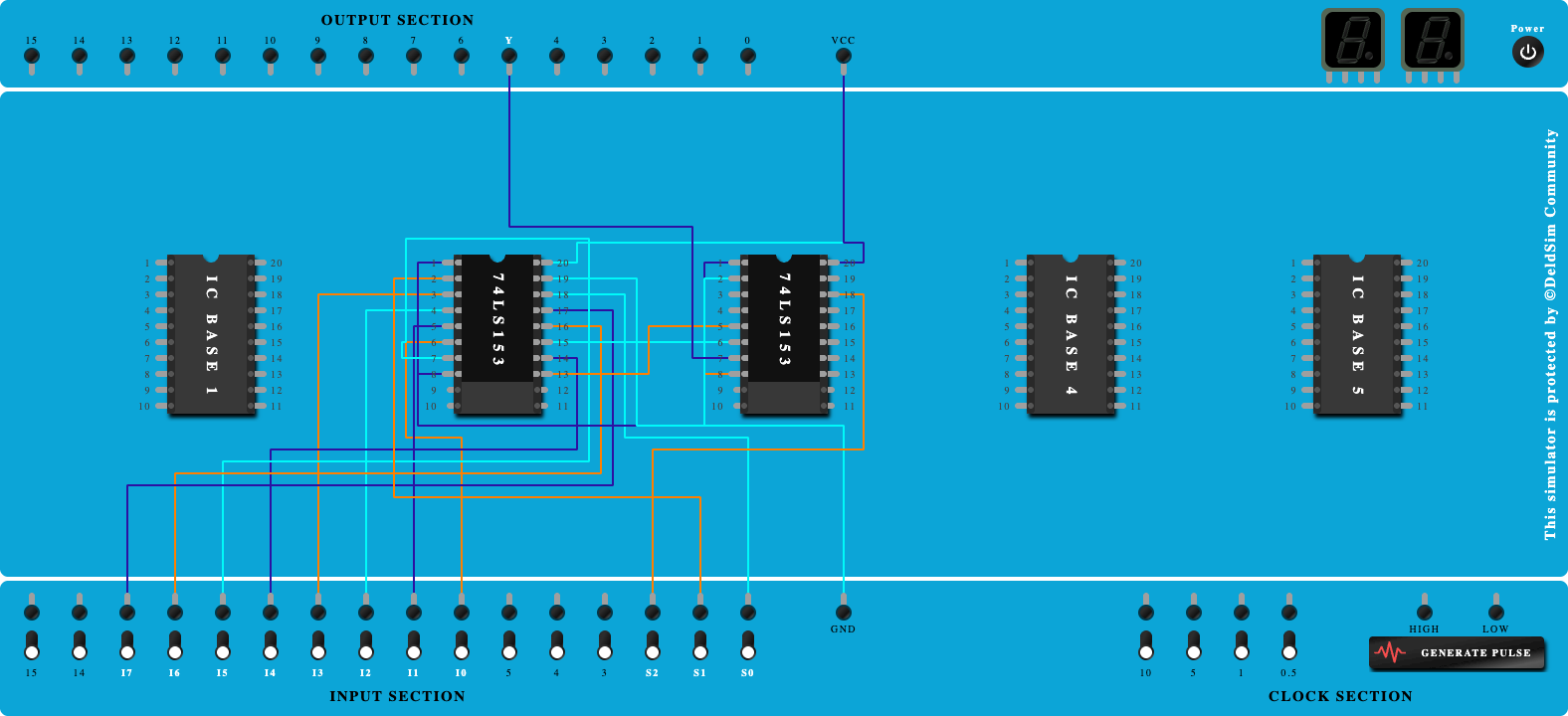
8:1 Multiplexer using IC 74LS153
To study and Verify the 8:1 Multiplexer using IC 74LS153.
